 Nathaniel Wong
Board Design.
We use Eagle to create our embedded board design, including version 1.0 and version 2.0 . Here is the version one, our first prototype for testing of images transmission.
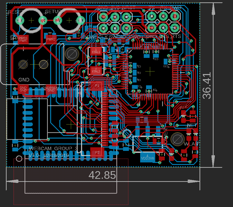
As we can see, this version includes WiFi module, MCU and camera module. Two buttons are used for reset and setup of WiFi chip. Moreover, two mountain holes are implemented to fix our board on the enclosure. However, our design still needs improvement, since PWM control are not included yet and size of the board is also not good for the final purpose. Then we developed our second version.
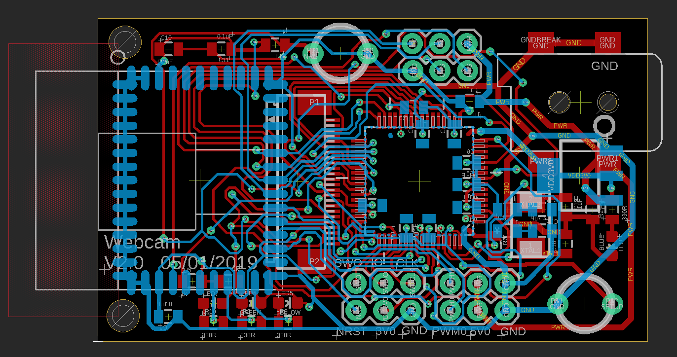
Version 2.0 is almost the same as the previous from components angle, however we still make a lot of progress in our design. First, two sets of PWM control headers are implemented, including 5V0, GND and PWM control signal. Also, in order to fit our board in to the pan-tilt base, we change size of the board. We make it slimmer, with 30mm width which is exactly the width of the pan-tilt base. Still we have some tiny parts to improve. For example, two PWM headers should not be so close to J-link headers, since it is not easy to insert two parts at the same time, which means we cannot download program and test PWM control at the same time. Well, it might not be perfect but still could be accepted, because we are 99% sure that our PWM control works well, we don't need to test them together. But from the application point of view, maybe in the next version we should fix this problem.
Image transmission using Camera Module.
The camera’s Zentri AMW004 wifi module, is able to receive more 3-4 image frames per second from the Microcontroller Unit (MCU). SPI is used for communication between the MCU and Camera module. Once the image is transmitted to the MCU buffer, the MCU is able to initiate a HTTP POST request through the AMW wifi chip via UART. We maximized the UART transmission rate by increasing the UART baud rate 8x faster at 921600 Hz rather than 115200 Hz, and reducing the size of the camera buffer to about 30KB (supports most 640x480 JPEG images).
Google Cloud server solution.
We used a micro EC2 compute to host a python Tornado web server, which is supported by OpenCV. The server scripts can be found in the GitHub repository.
Tornado web server.
The cloud server receives all images via HTTP POST and performs person recognition and tracking in real time for a single camera. Once the coordinates and size of the person are determined, a PID controller determines the angles that pan-tilt base should now adopt. These values are transmitted via a HTTP RESPONSE to the camera using the same TCP connection.
Web Client
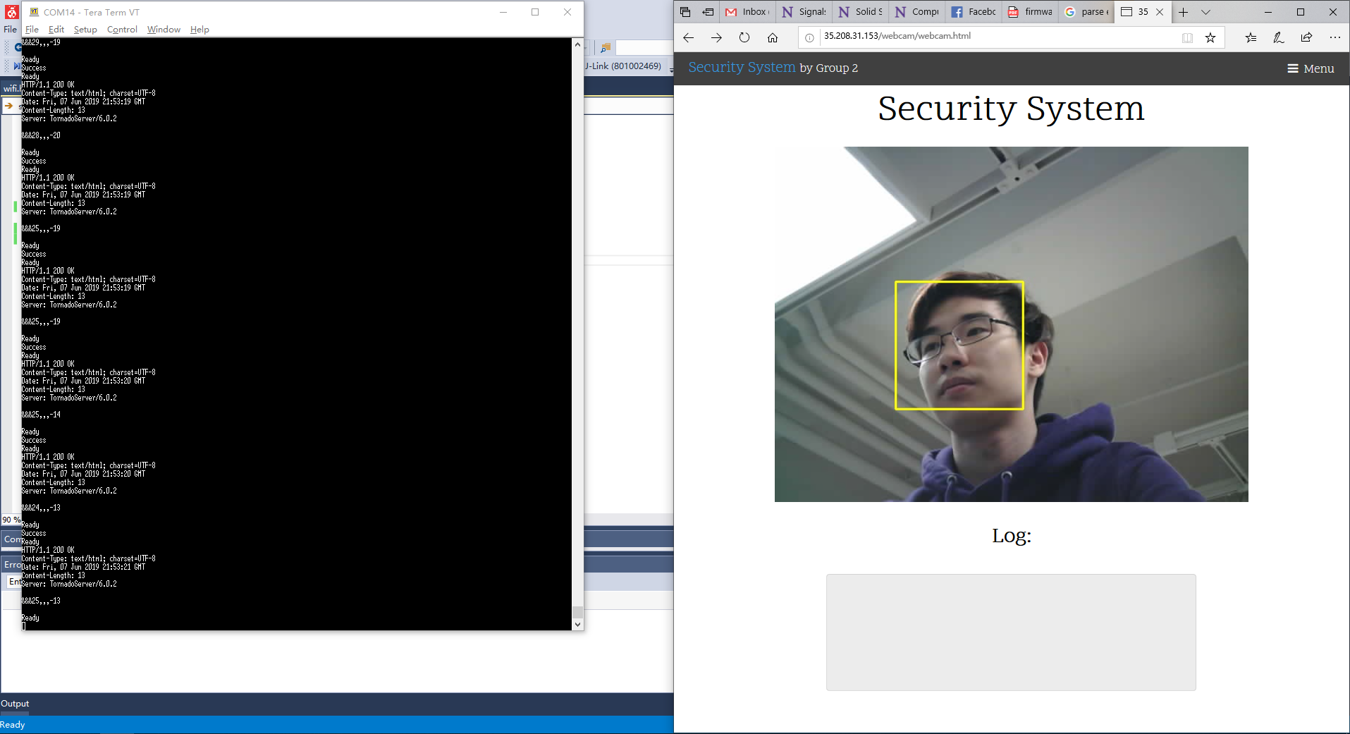
The Python server script offers a simple web interface from which to view the image stream. This was achieved using a javascript function that refreshed the JPEG image every 100ms and a browser cache bypass.
OpenCV detection and tracking.
We used OpenCV Haar-Cascade feature identification and MOSSE tracking to detect and track people as they move across the room. Haar-Cascade detection is used to identify faces (frontal and profile), half body and full body to a reasonable degree of accuracy. Once a region of interest is identified, a MOSSE tracker follows the person, identifies the appropriate bounding box and overlays the bounding box graphic on the JPEG image, while updating the PID controller accordingly.
PWM servo actuators.
This part is relatively easy, because we could use example file in the Atmel Studio. We need to define pins of MCU to work as PWM mode, and follow the configuration from the example code, things are gonna be fine. The PWM servos now respond accordingly to the angle values provided over the HTTP RESPONSE from the server. The MCU receives and calculates the appropriate duty cycle level for each servo.