 Kevin Kessler
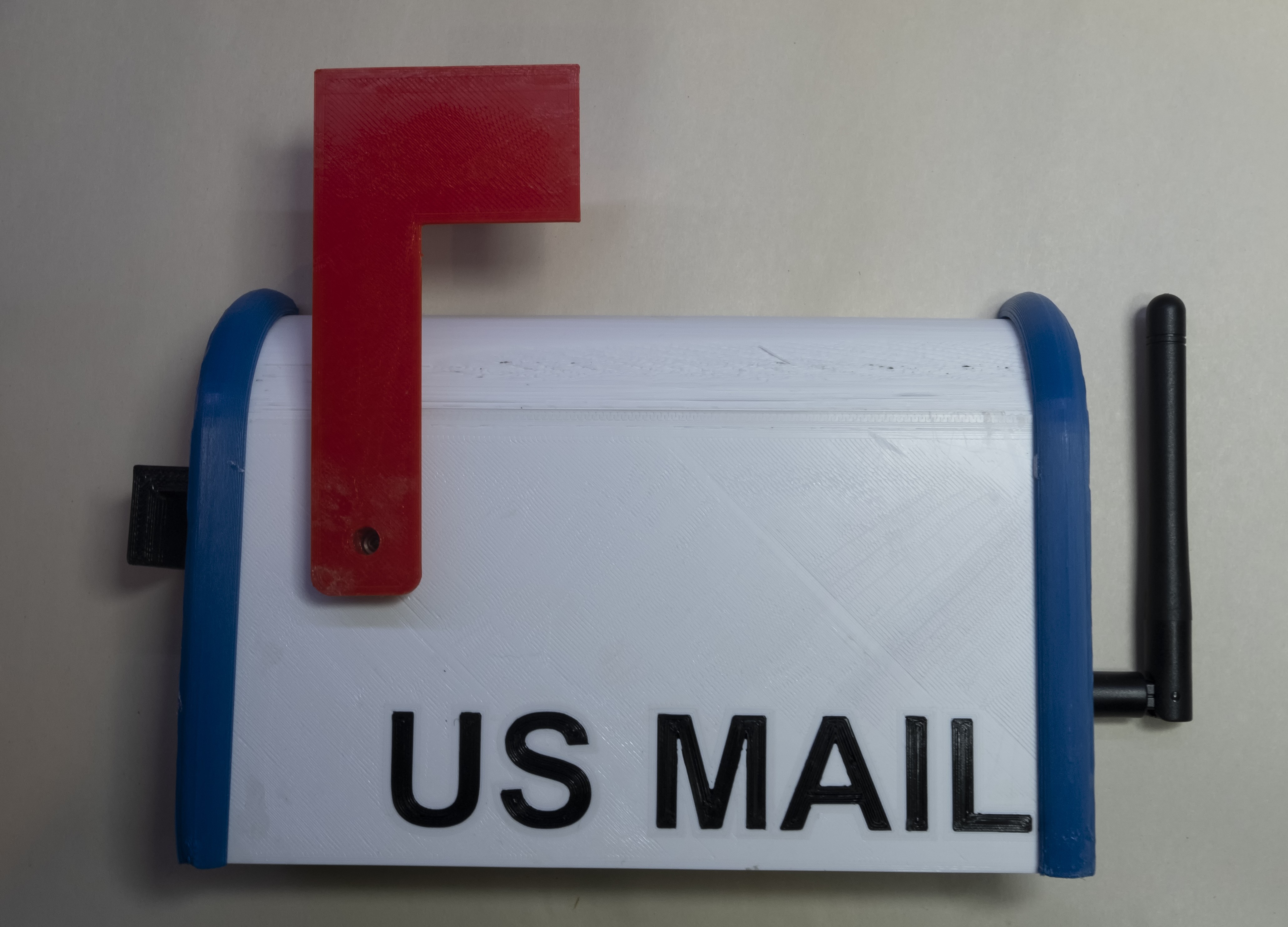
The purpose of this project is to instrument my mailbox with sensors so mail can be detected when the mailbox is full, and a 3D printed display mail box can raise its flag.
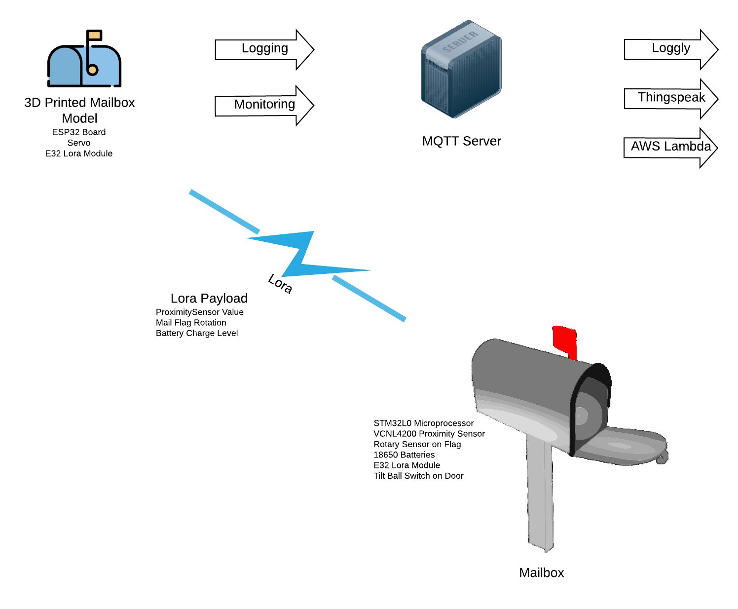
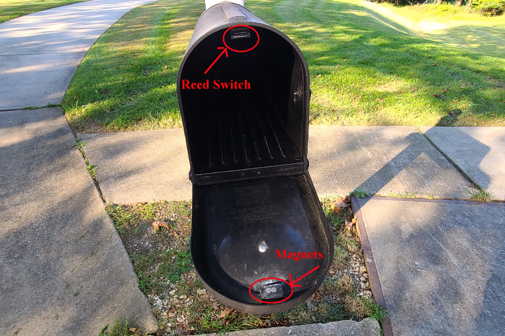
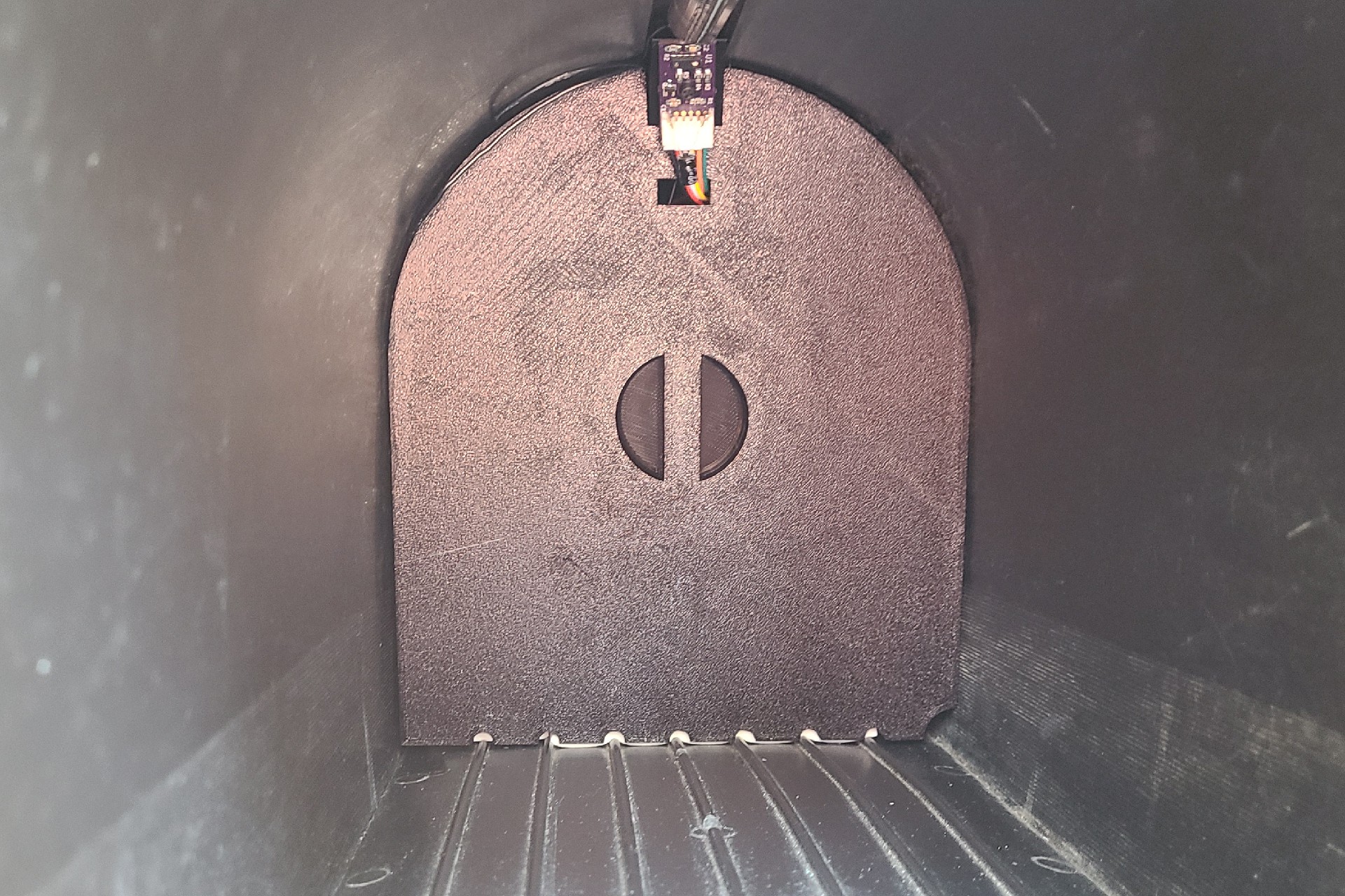
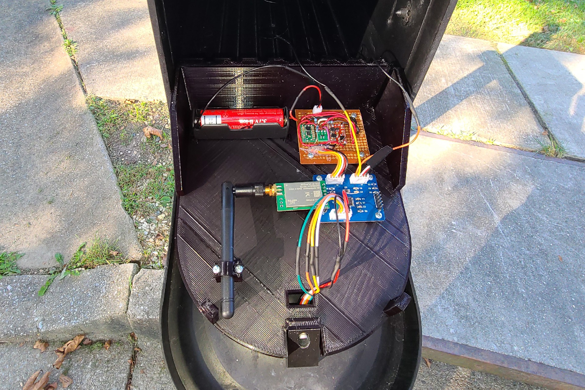
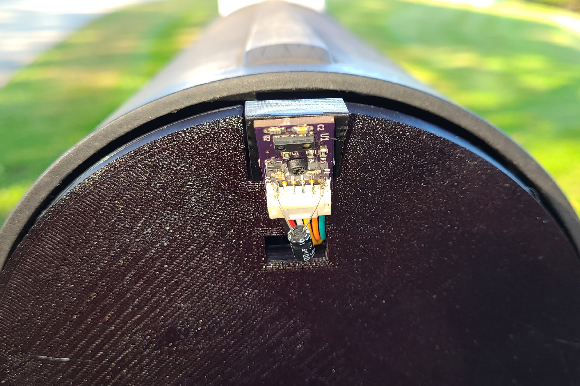
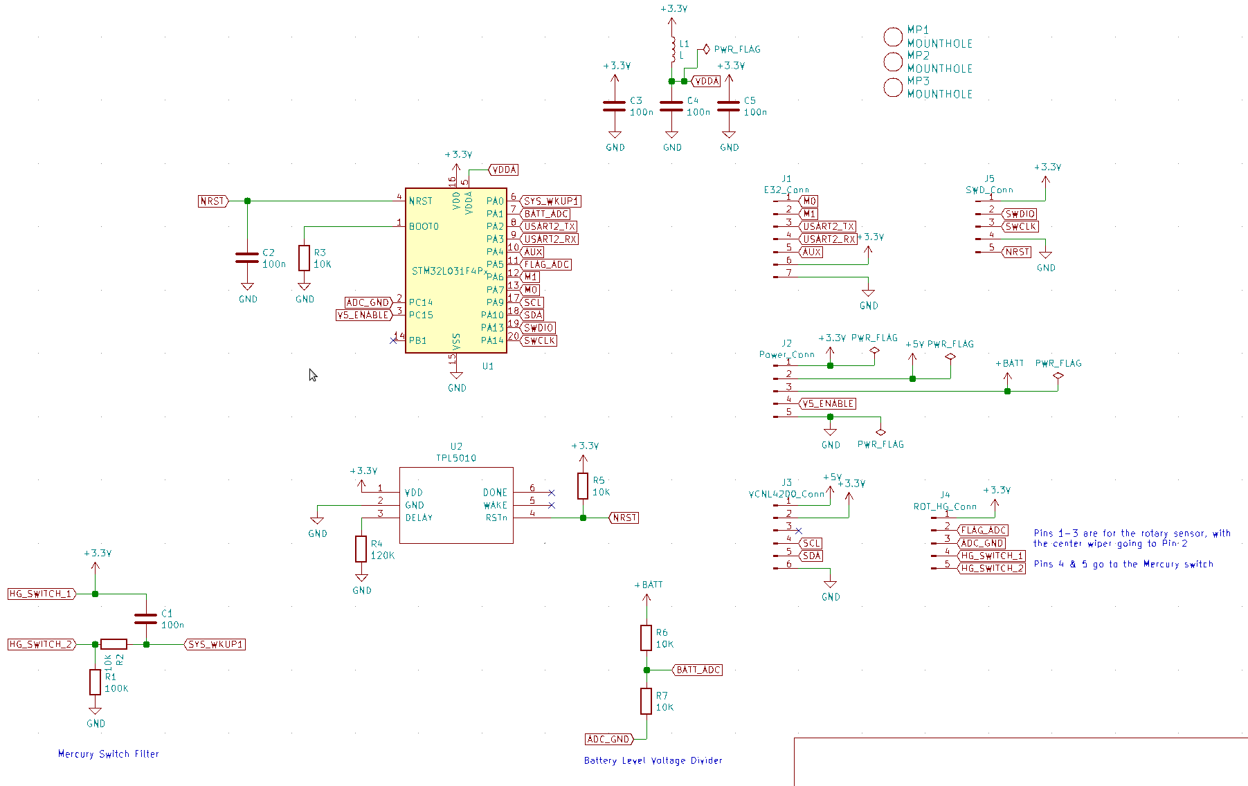
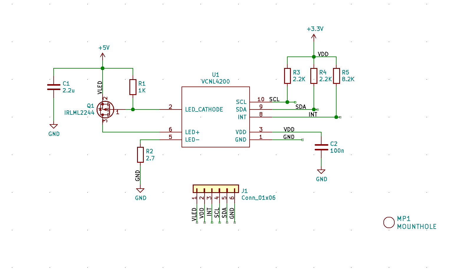
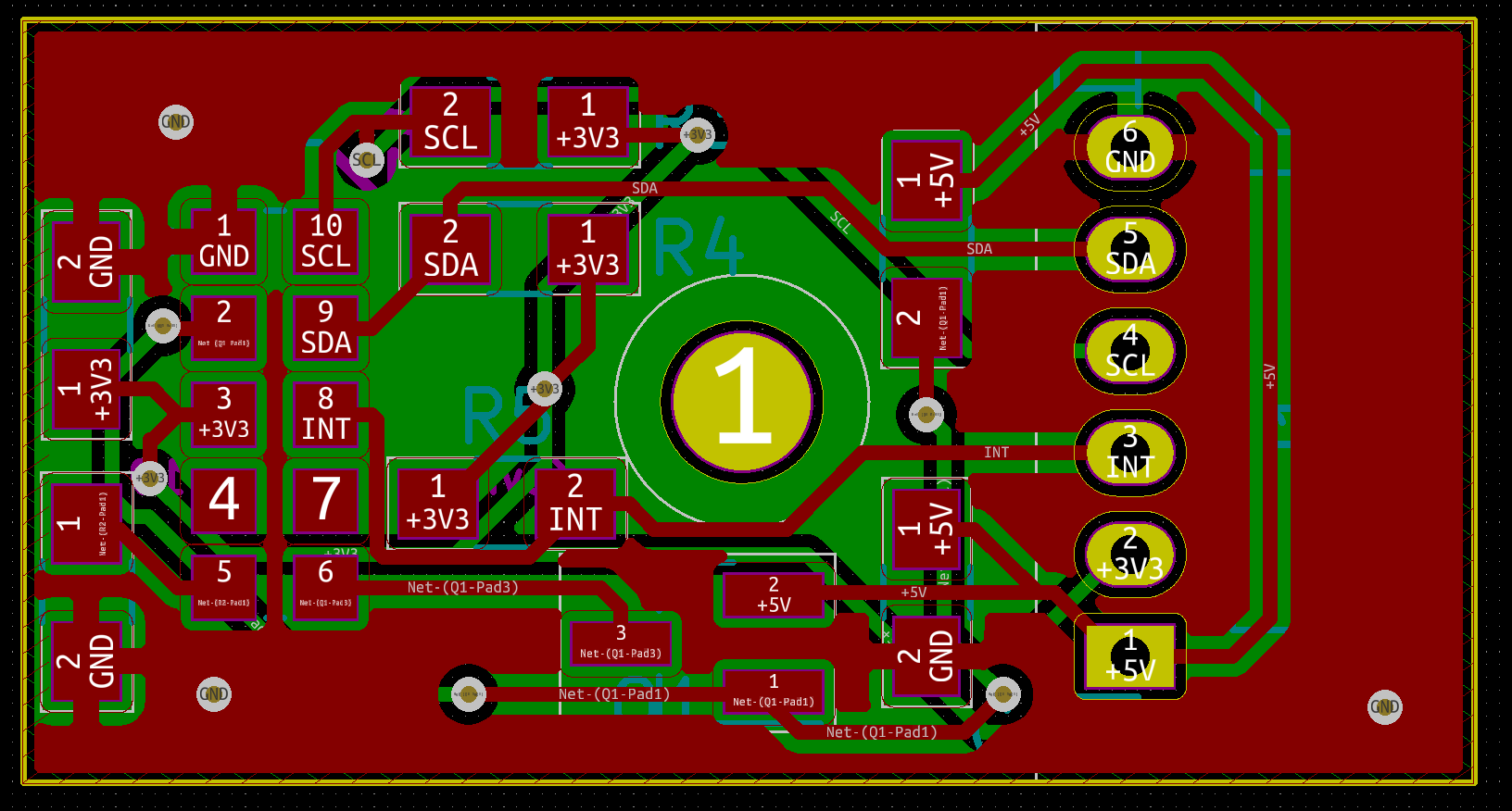
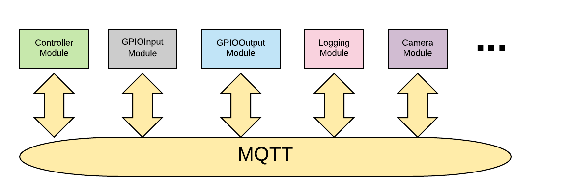
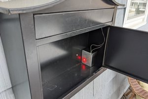
A Tilt Ball Switch is attached to the mailbox door A reed switch on the mailbox and a magnet attached to the door, to detect when the door is closed. Closing the door triggers the VCNL4200 Proximity Sensor. The proximity sensor has an IR transmitter and receiver, and the difference between the IR reflectivity of the empty mailbox, and a mail filled box is quite measurable. The sensor has an I2C interface, and returns a value proportional to the reflected IR signal from the emitter. The STM32L0 uController runs the show, and will read that value from I2C, as well as the position of the flag through the ADC and a rotary sensor. If the flag is up, then the mail in the box is meant for the postman, and should not trigger the display on the wall of the garage.
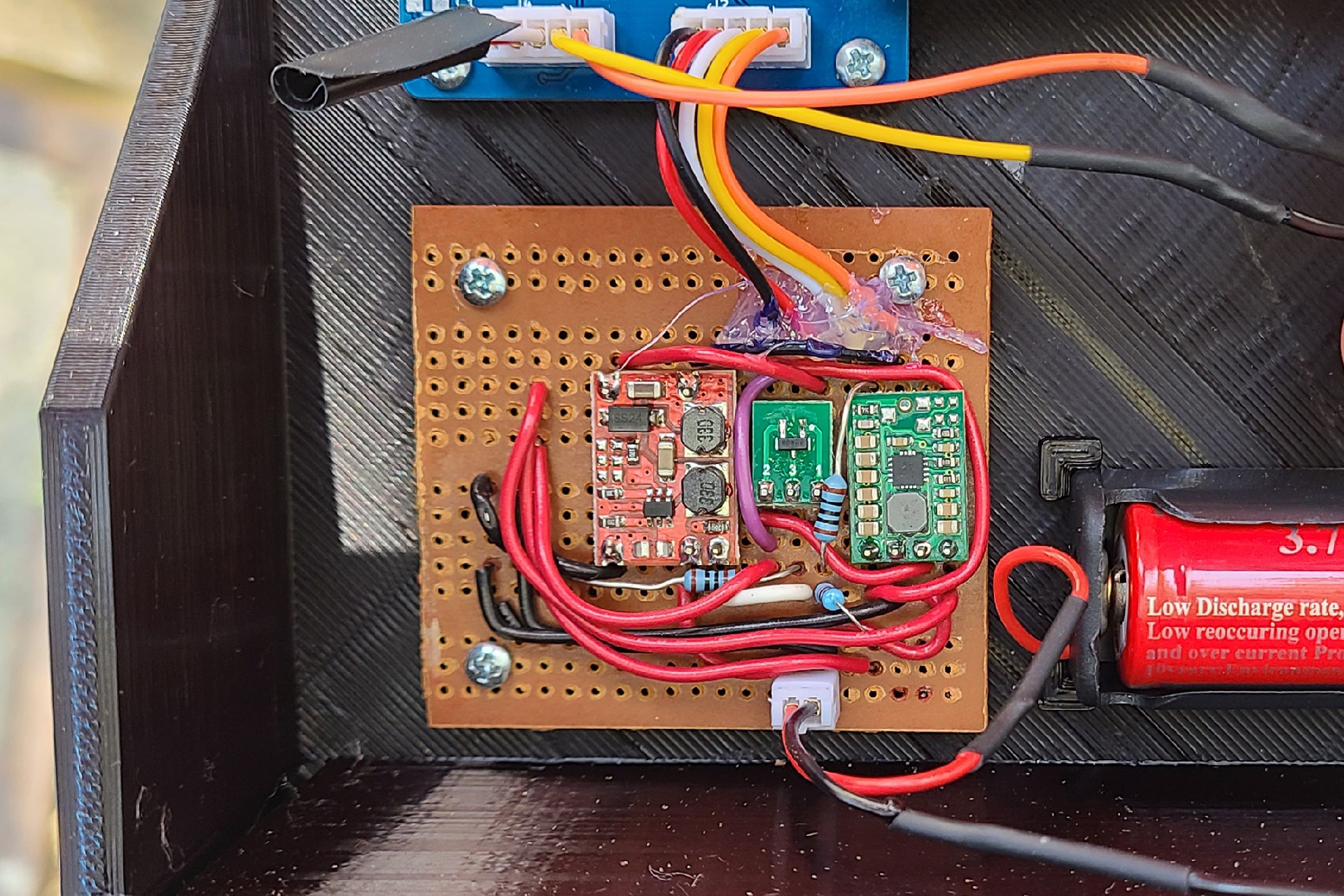
Communication to the base station is done over Lora with E32 Lora modules. These modules communicate to the uController over a UART, and contain the firmware handling of the Lora radio. This simplifies the Lora communication. The mailbox instrumentation will send the raw values from the Proximity Sensor, the Rotary Sensor, and the battery voltage to the base station, which can use that information to decide to raise the flag. The raw values are sent to the base station, because it is far easier to update the firmware on the ESP32 module on WiFi to tweak settings, than it is to update the firmware on the remote STM32.
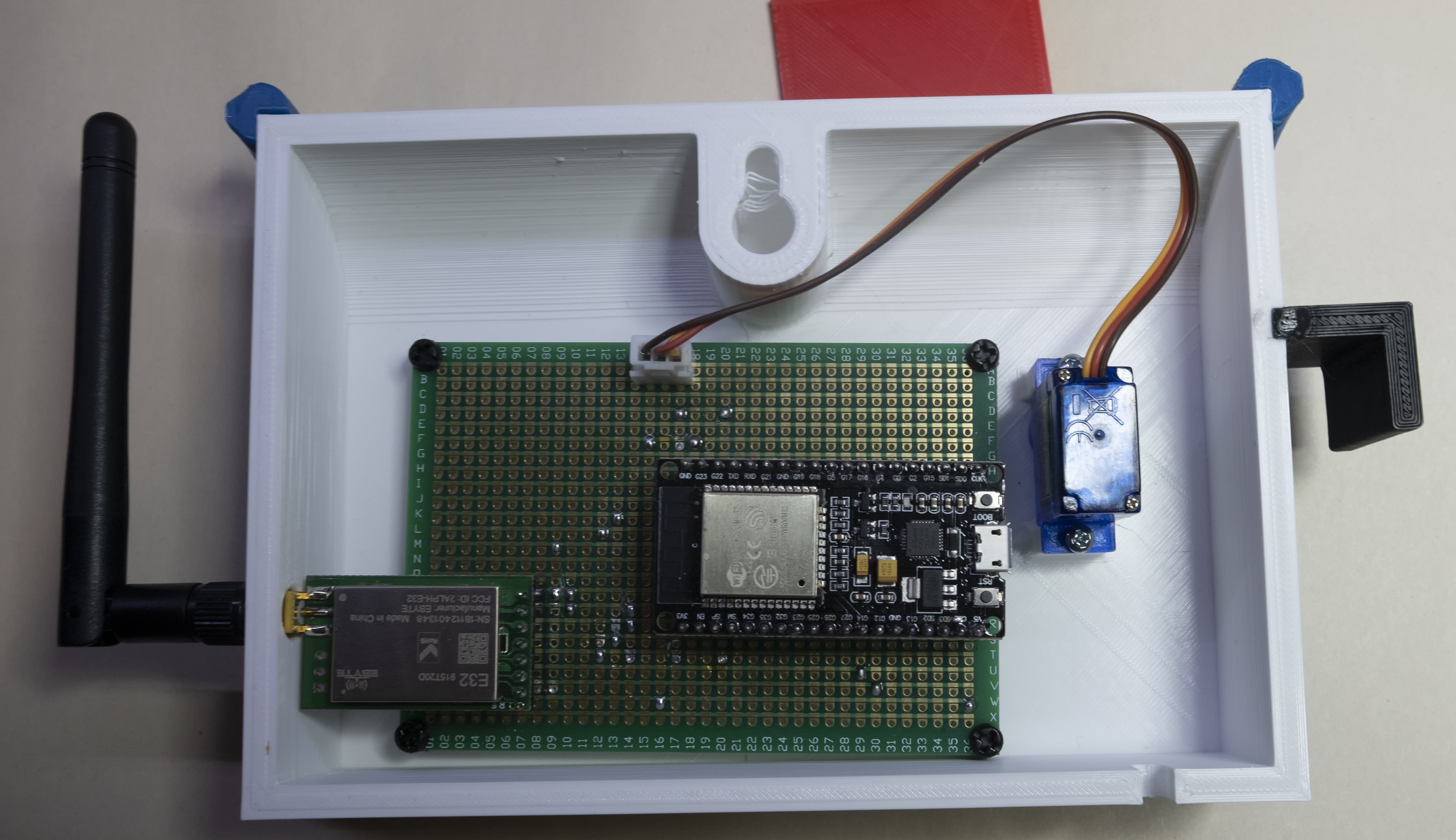
The base station consists of an ESP32 modules, another E32 Lora module, and a hobbyist servo. On receiving a Lora message, the ESP32 will decide whether to raise the flag.
The ESP32 also connects to an existing MQTT server, which I use to automatically close my garage door, among other things. This MQTT server provides communication for logging, thought loggly.com, and monitoring with thingspeack.com. It is also responsible for sending a text message when the batteries are low, as well as monitoring the heartbeats to ensure both the basestation and remote mailbox are running.
The ESP32 base station connects to the MQTT server supporting my existing Home Assistant server. Home Assistant provides the logging, monitoring and alerting for the mailbox system.
 Ben Brooks
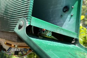
 Rex Garland
 Harri Ohra-aho
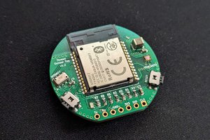
 Wassim