 Kevin Kessler
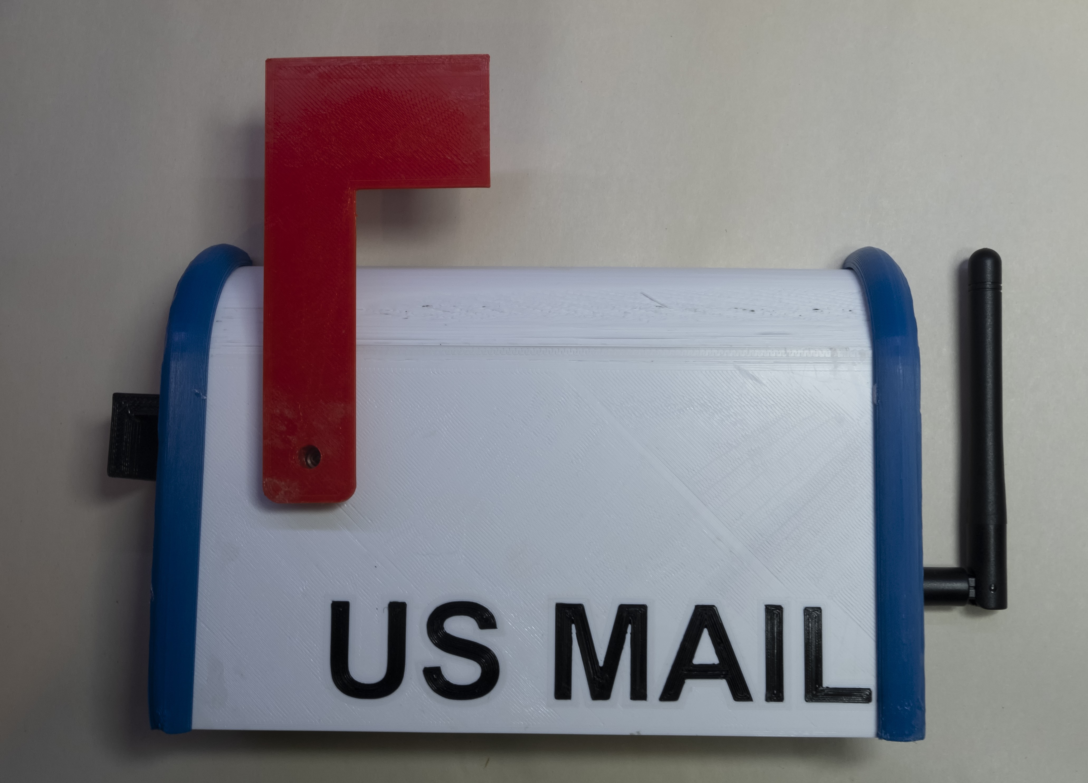
The ESP32 base station receives the Lora transmissions from the mailbox sensors and indicates the state of the mail with a servo attached to a flag. The base station also forwards the state of the sensor to the MQTT server for further processing. The MQTT server logs the sensor values to loggly.com, and plot the temperature and voltage data on Thingspeak. The base station also periodically sends a heartbeat to the MQTT server (indicated by a sensor value set of all the lowest values). The MQTT server monitors this heartbeat, and will text my phone if the heartbeat goes missing for long enough.
The base station code is written in the Arduino core. I normally avoid the Arduino programming model, mainly because I despised the Arduino IDE. I've discovered the PlatformIO IDE, and I'm pretty happy with it; so much so that I've written the STM32 CubeMX code for the Mailbox Sensors with it as well, instead of Eclipse that I use for pretty much everything.
In order to configure the device, a SPIFFS file system is created with a JSON file that looks like:
{
    "ssid": "xxxxxxxx",
    "password": "xxxxxxxxxxxx",
    "pskIdent": "xxxxxxxxx",
    "pskKey": "xxxxxxxxxxxxxxx",
    "mqtt_host": "xxxxxxxxxxxxxx",
    "mqtt_port":  8883
}
This is filled out with the wifi credentials and the pre-shared key and address of the MQTT server, and saved to the data directory. The github repo contains this file in a data_model directory, but the actual filled out version must go into a data directory at the same level. I do this so I don't accidentally upload my wifi credential to github. The SPIFFS file system is uploaded separately from the code with the command:
platformio run --target uploadfs
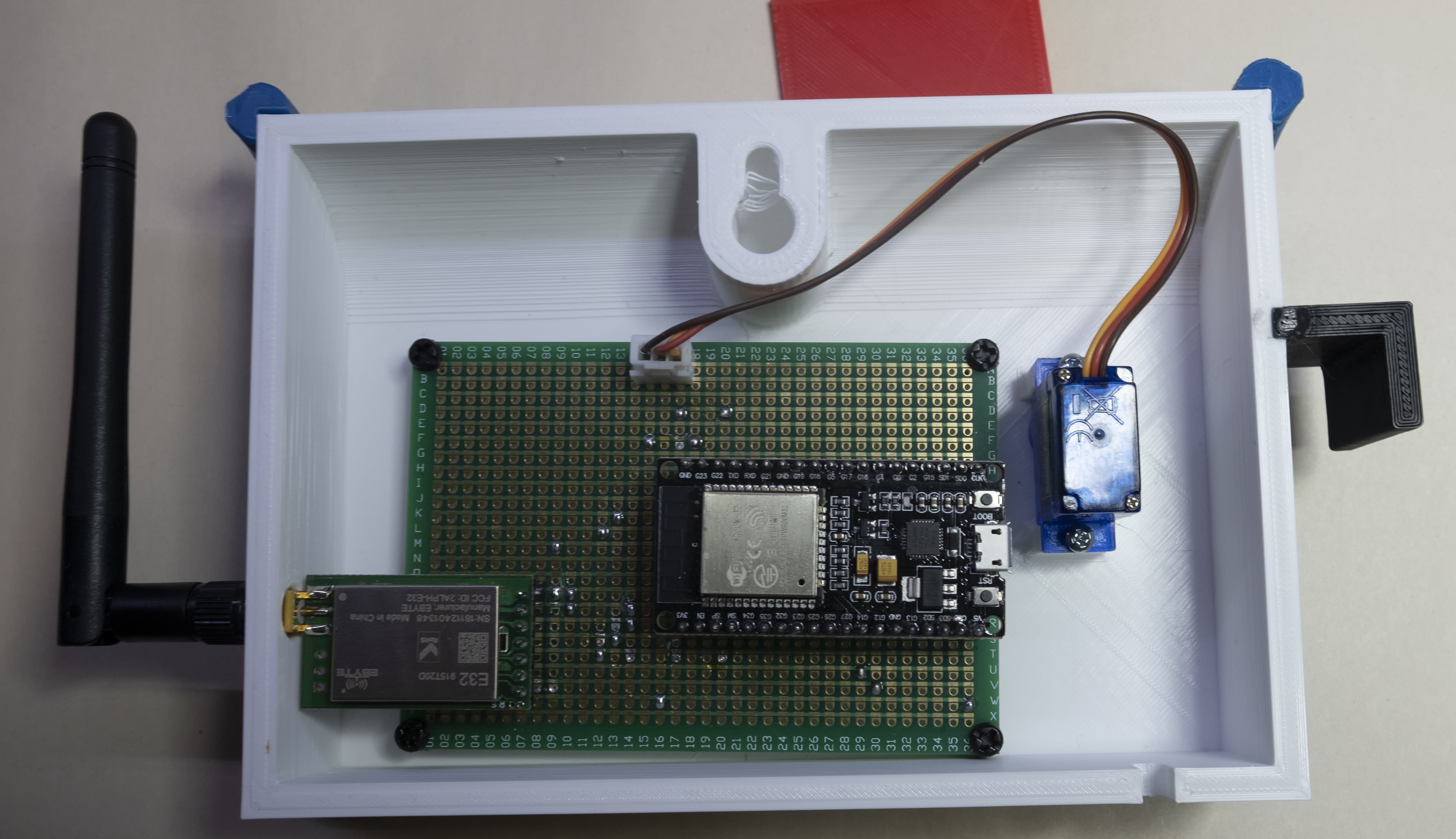
The PCB is rather large and would have been expensive to get created at OSHPark so I decided to try some Perf+ boards boards I had lying around. The Perf + PCB uses perpendicular traces and solder bridges to route signals between endpoints. The software Perfy assists in routing traces and deciding where to put the solder bridges.
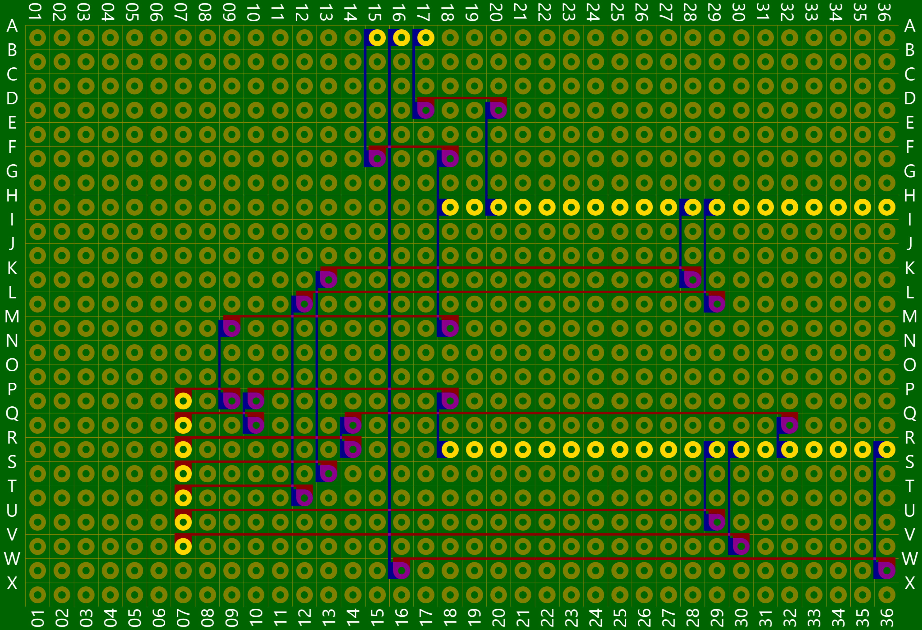
This type of PCB works because the circuit for the base station is so simple. An ESP32 Dev Board drives an E32 Lora Module through the second UART, and a servo runs through PWM of a GPIO.
Discussions
Become a Hackaday.io Member
Create an account to leave a comment. Already have an account? Log In.