*BLEthingy* is a battery-powered, wireless sensor node device. The device is powered by a CR2032 coin cell battery and is designed to consume as little power as possible. Wireless connectivity is provided via Bluetooth Low Energy (BLE), which allows for low-power transmissions e.g. as a so called [Beacon](https://en.wikipedia.org/wiki/Bluetooth_low_energy_beacon). The BLE functionality is provided by a RN4871/I module. It communicates via UART with the main microcontroller. The microcontroller used is an ATtiny3216 which is part of Microchip's new tiny-1 series. Despite the name, it's very different than the previous ATtiny's (like the ATtiny85, ATtiny13 etc.) and has a lot more features and peripherals. Another feature I wanted to include is motion detection, for this purpose an accelerometer ADXL345 is used. In this part I'll talk about the hardware design of the device.
**BLE module RN4871/I**
This module provides the BLE communication for *BLEthingy*. It communicates with the ATtiny3216 via UART with commands (like using the terminal on the PC). Additionaly the reset-pin and the wakeup-pin of the module are driven by the microcontroller. Using the wakeup-pin, we can put the RN4871/I to sleep and wake it up if we need to. This way we can minimize power-consumption drastically. The module is mounted on the PCB with castellated pads. During the PCB layout, it was necessary to respect some special requirements. There are areas beneath the module that shouldn't be filled with a ground plane, luckily in the KiCAD library the component was already available and the footprint was correct. Additionally, the datasheet advises to let the antenna side of the module stand out of the PCB for better performance. In my case I didn't do that because I wanted the PCB to be round. Instead I added a cutout in the PCB beneath the antenna area.
Soldering the module by hand turned out a bit tricky because of the fine pitch of the pins, but in the end it turned out ok.
**microcontroller ATtiny3216**
The ATtiny3216's UART lines are connected to the RN4871/I module. The ADXL345 accelerometer is connected via SPI. Additionally, a small pushbutton and an LED are connected to the GPIO pins.
One thing to note is that the ATtiny3216 (like all members of the new tiny-1 series afaik) uses a new programming interface called **UPDI** instead of the the old **ISP**. One advantage of it is, that it uses only a single pin (in addition to ground and Vcc naturally). Alas, I feared that I would need a special programmer. Luckily I found the [**pyupdi**](https://github.com/mraardvark/pyupdi) project. As it turns out, the UPDI protocol can be implemented using a simple USB-Serial adapter by connecting the TX and RX lines with a resistor. Then using the pyupdi python script, the program can be flashed. It worked very well, with minor inconveniences: for me, it worked only with a low baud rate. Thus, programming took quite long. Sometimes it happened, that after programming a few times, it didn't work anymore. Then I had to unplug and plug in the USB again for it to work. But still it is a great project that allows to use these new microcontrollers without buying a dedicated programmer.
**accelerometer ADXL345**
The ADXL345 is a 3-axis accelerometer. It can communicate via I²C or SPI, I chose SPI because of the much higher data rate. This means that the microcontroller and the accelerometer have to stay awake for a much shorter time period which reduces power consumption. The ADXL345 comes in a really tiny package, which is almost impossible (for me at least) to solder by hand. Thus I chose to use a breakout board with the accelerometer and mounted the board on the PCB with pin headers. I used a breakout board named *GY-291* which can be found easily and is very cheap (almost the same price as the accelerometer itself in sigle quantity!). To use the breakout board, I had to modify it slightly: the GY-291 board has a 3.3V voltage regulator which I didn't...
Read more »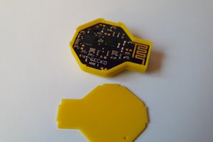
 Max.K
Max.K
 Ben Lim
 Kris Winer
 novirium