 James Fowkes
Basics
The core of the electronics is a simple op-amp voltage follower:
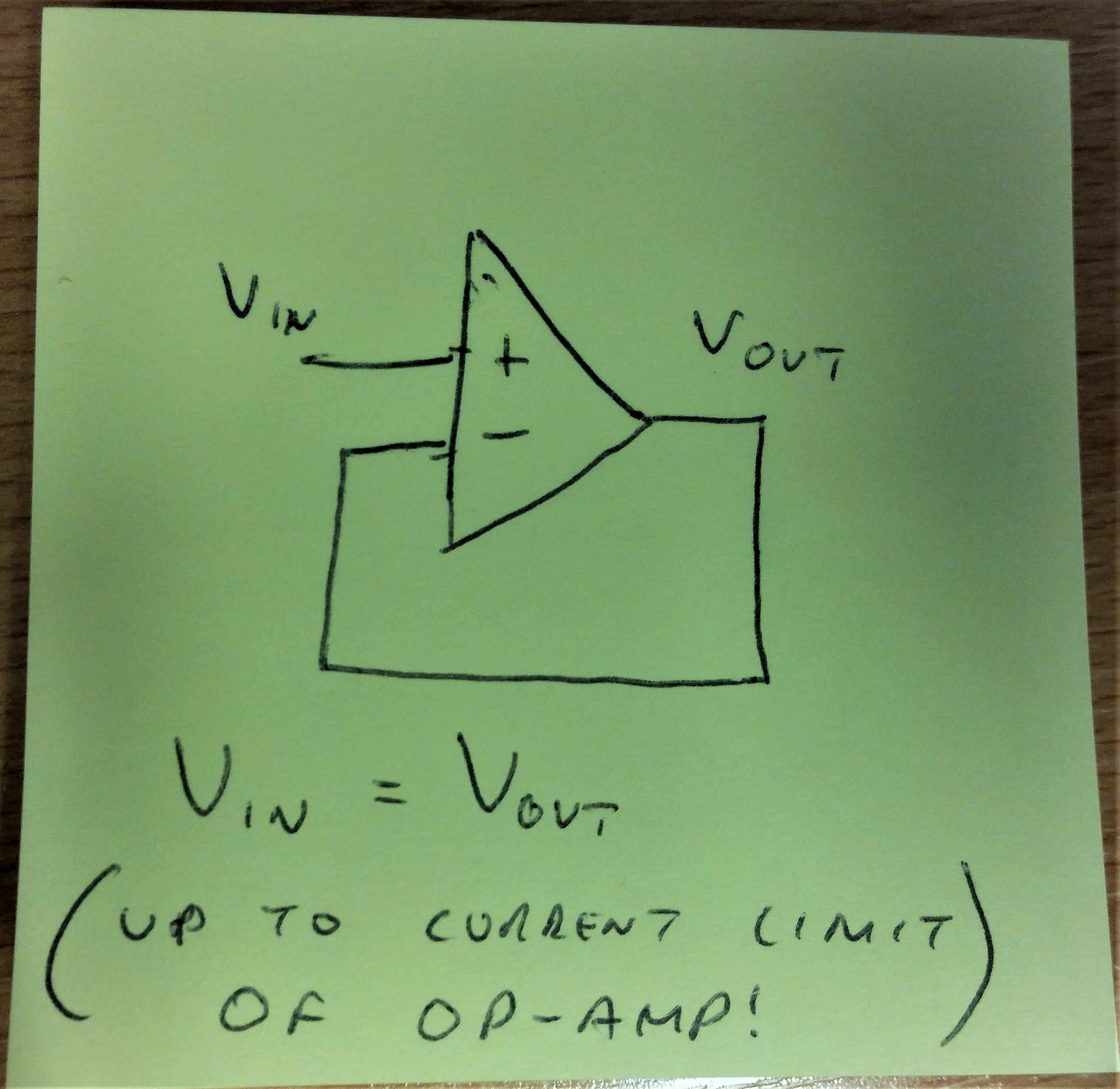
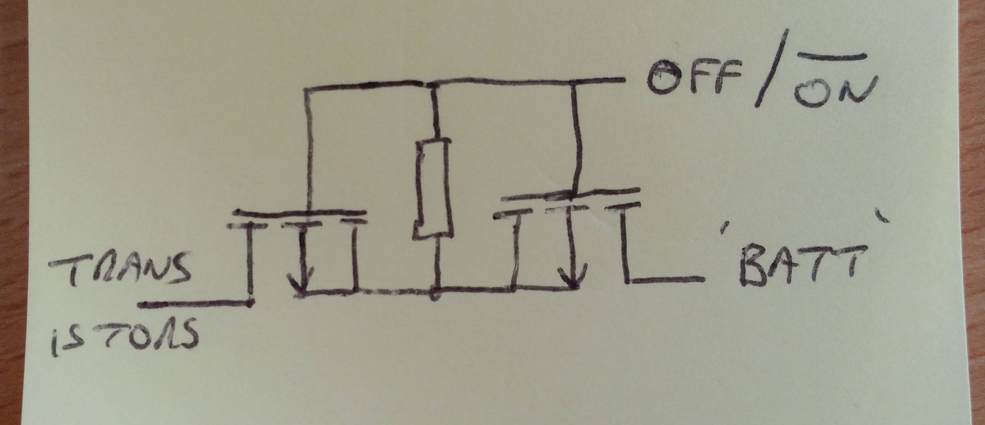
But I need to supply up to 1A, which (most) op-amps can't do. So, the next step is to buffer the voltage with two bipolar transistors. This is a classic "push-pull" class-B amplifier arrangement:
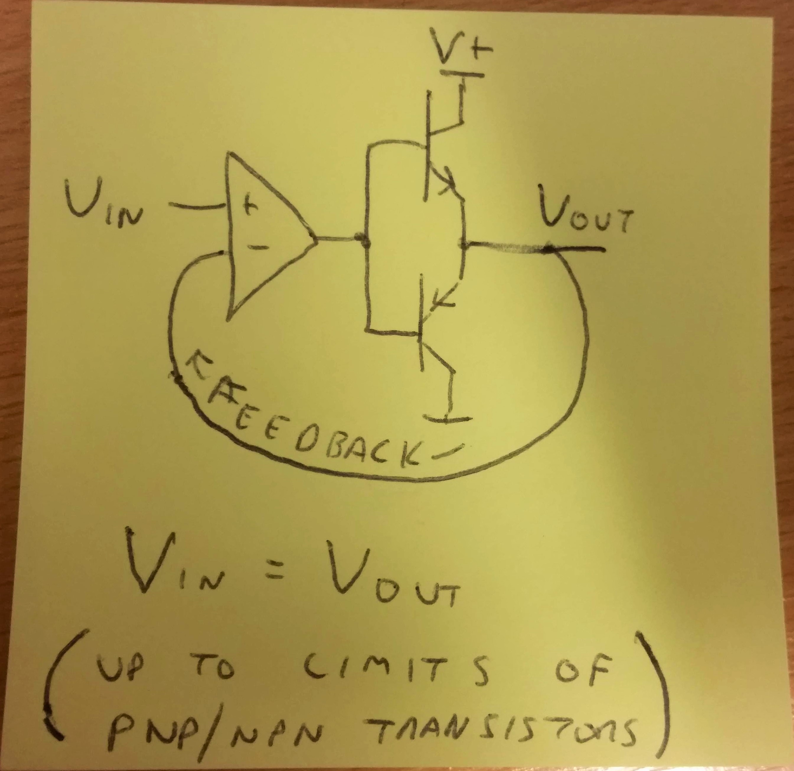
(*also up to limits of power supply, wiring, etc, etc...)
If the "battery" is being discharged, the op-amp will raise its output voltage, causing the NPN to turn on and feed current from the supply.
If the "battery" is being charged, the op-amp will lower its output voltage, causing the PNP to turn on and pull current from the charger.
Inputs and Outputs
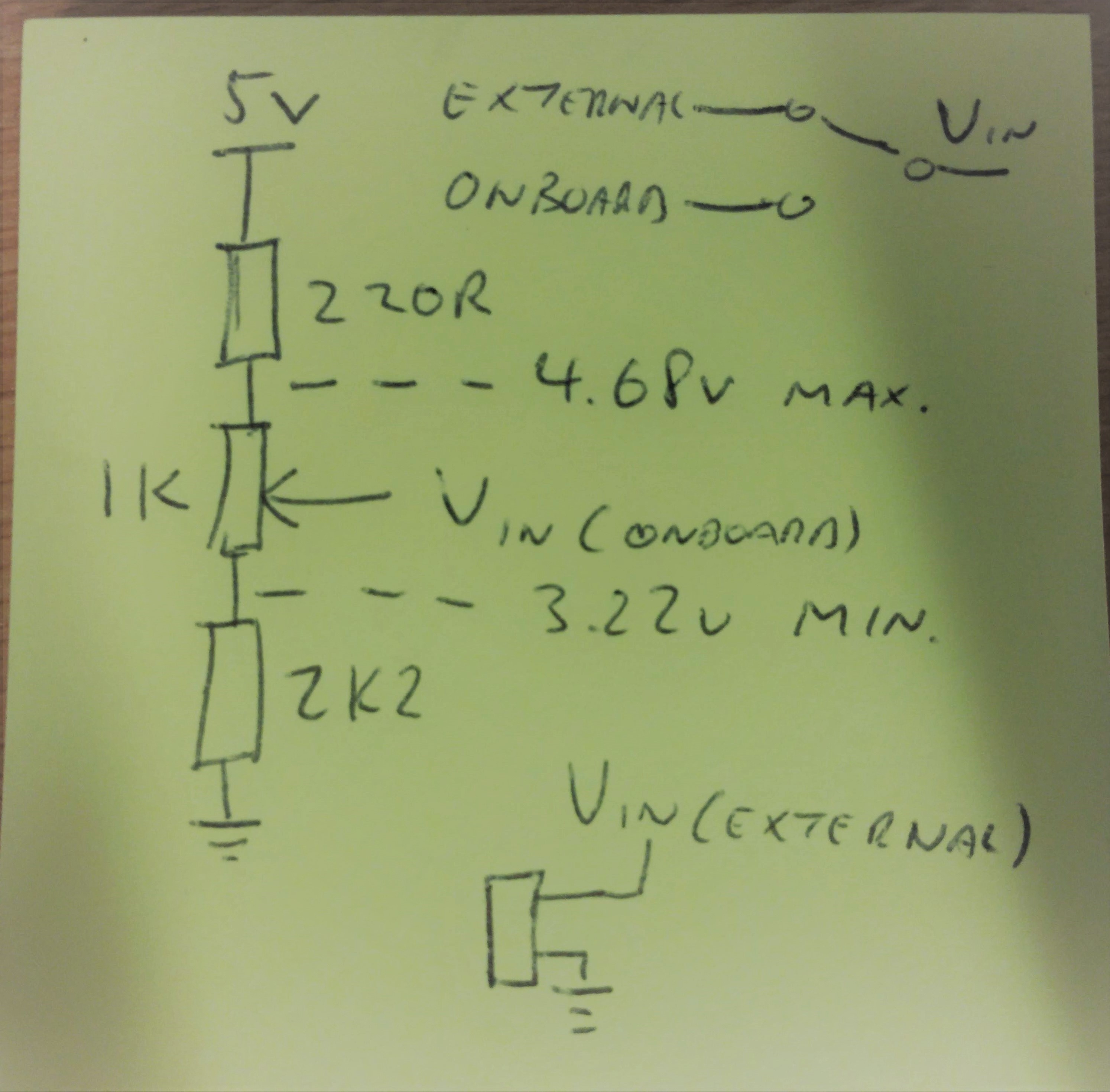
In general I want each battery "variable" (voltage, temperature and "is it connected or not") to be controllable from both on the board and from an external source (like an Arduino or whatever - the possibilities are endless).
So, the VIN control voltage comes from an onboard potentiometer or from an external connection:
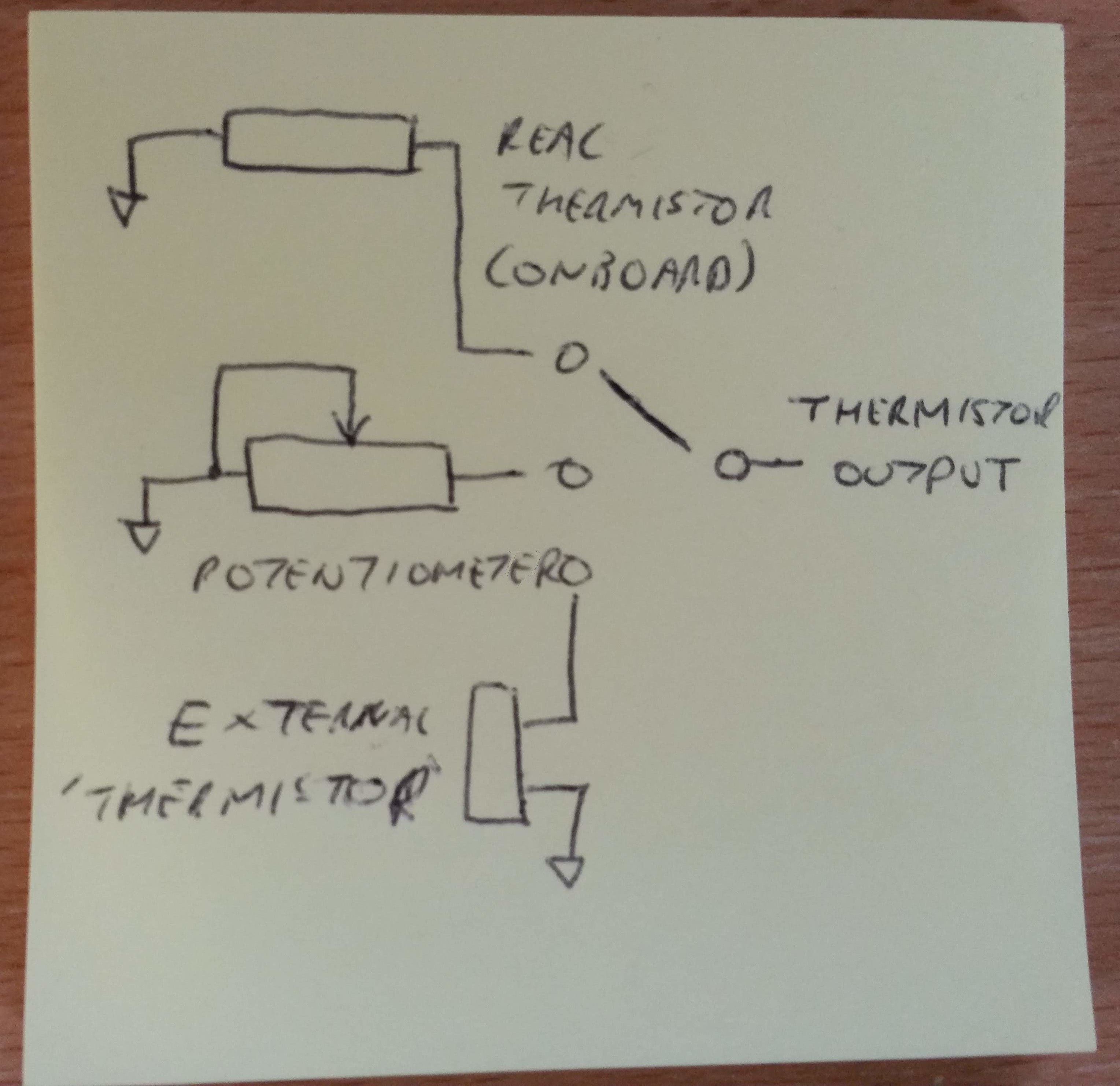
Likewise, the temperature has three possible sources: an onboard thermistor, and onboard potentiometer or an external resistance (an actual thermistor or potentiometer):
Connect/Disconnect
I want users of the board to be able to simulate connection/disconnection of the battery without physically removing the connection. This is helpful for doing automated testing, and just to avoid constantly handling connectors.
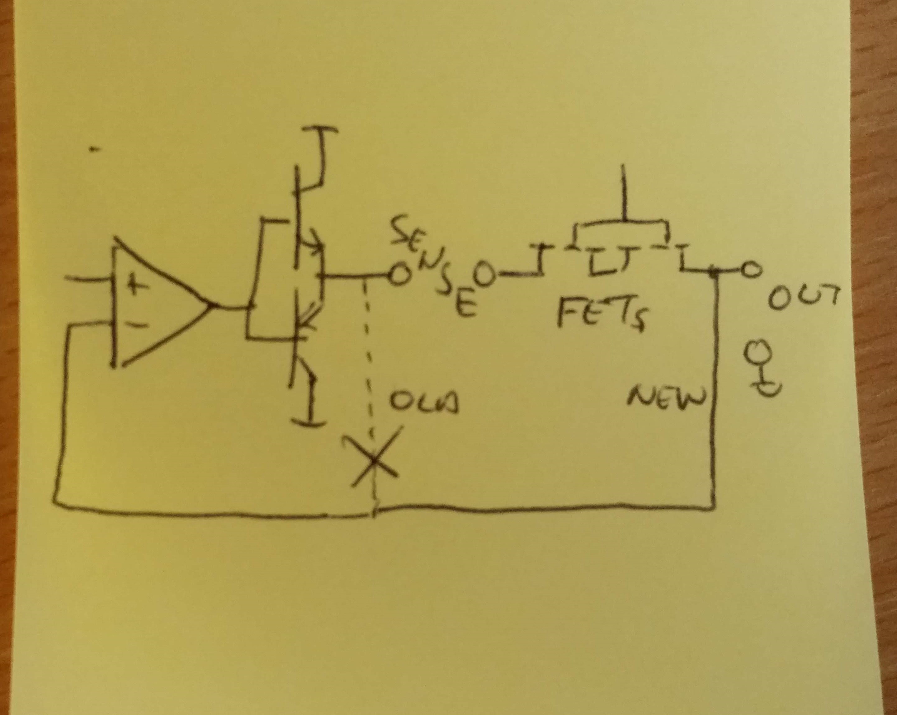
So, between the transistors and the battery connector, there will be a pair of back-to-back P-channel MOSFETs. They will pass or block current under the control of an external signal:
Voltage and Current Sensing
I don't want to put any sensing or displays on this board as it adds to cost and complexity. So, the board will have 4mm connectors for current sensing and for voltage. The current sensing will need a header or switch to short out the connectors if they are not being used.
Feedback Issues
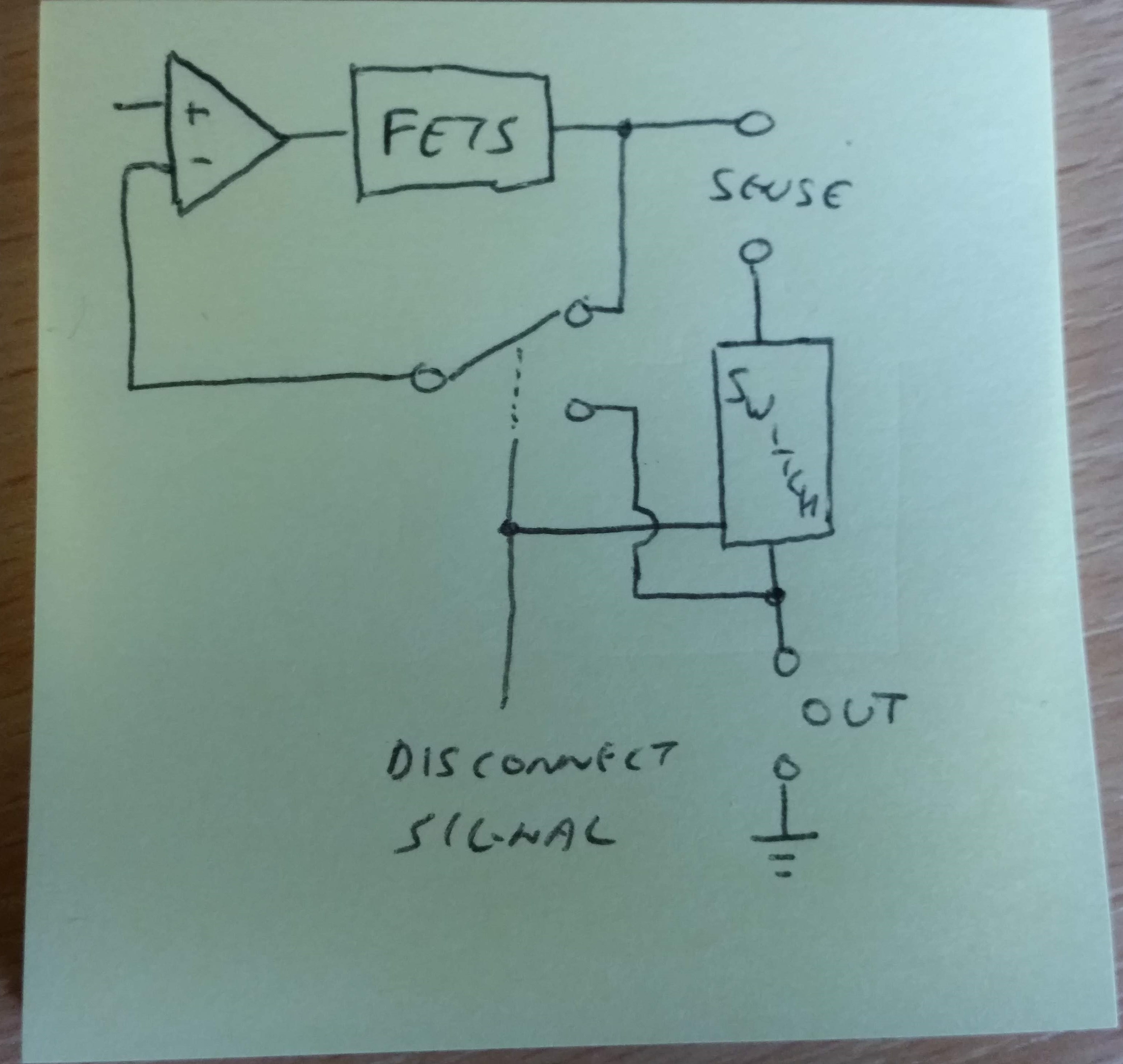
The back-to-back MOSFETs and the current sensing presents an issue: the in-line resistances will reduce the output voltage below that being set. So, I could move the op-amp feedback from the transistors to the battery output itself:
But, this means that the feedback signal can be broken, which may result in undesired current flows or voltages. So, we fit an analog switch that will automatically select the correct source for the feedback voltage:

 Stefan Wagner
 George
Hi, have you made a proto? I am in the need of the same emulator and started to build one based on an Adruino, 2004 display, analog circuit able to push and pull up to 1 amp in the range of 0.5V to 4.5V, and measuting current. Will share it soon.