 I'm a maker
For my CNC router, I'm in need of a method to hold my workpieces. Sticky tape does work, but it is a pain to remove it after milling. Furthermore, the presented method of NYC CNC using superglue also does work very well, but it requires lots of preparations, namely, very clean surfaces, tape has to be applied accurately to both, the workpiece and the mounting plate, glue has to be applied to the workpiece, accelerator has to be applied to the mounting plate and finally, after all that preparation, it is important to align the workpiece quickly before the glue fixes the workpiece in place.
Thus, a vacuum table is a very smart choice to fix workpieces quickly and safely to the mounting plate. There are different choices for vacuum tables, but I decided for a "breadboard" style table, since it is quicker to use. Sebastian End of END CNC has shown the easy use of a breadboard style vacuum table.
The CAD design is already close to finish while starting this project on Hackaday. We decided for a size of 450mm x 300mm, because 300mm is close to the limit of our CNC machine in one direction. The limit of the other direction is chosen like this, because we wanted to have free space beside the vacuum table, e.g. for a vice. Furthermore, we the following specs and features we would like to have in our vacuum table:
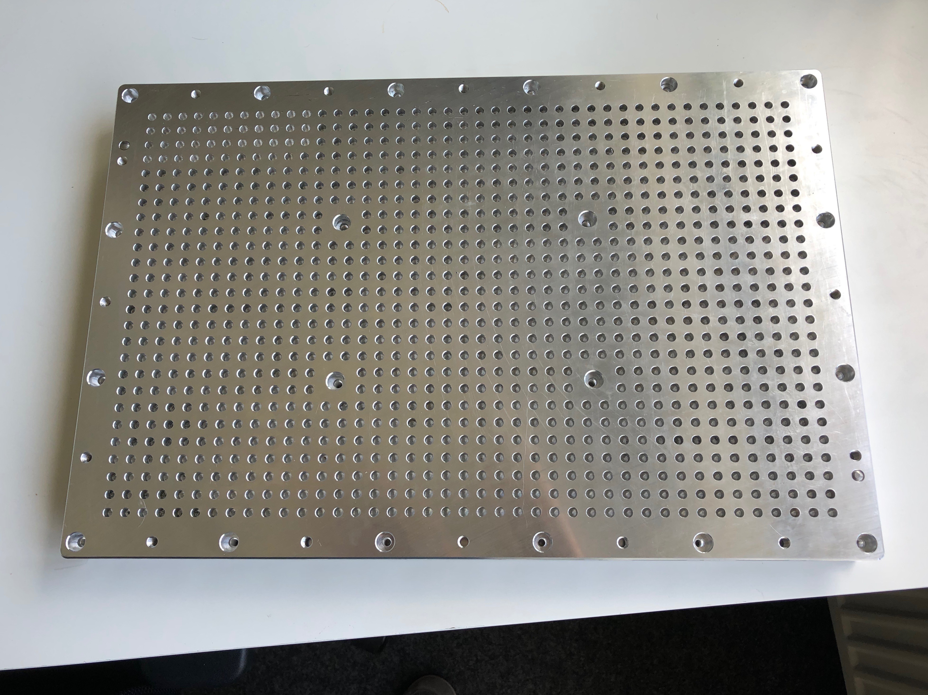
- 450mm x 300mm x 31.5mm dimensions (height resulting of the available aluminium)
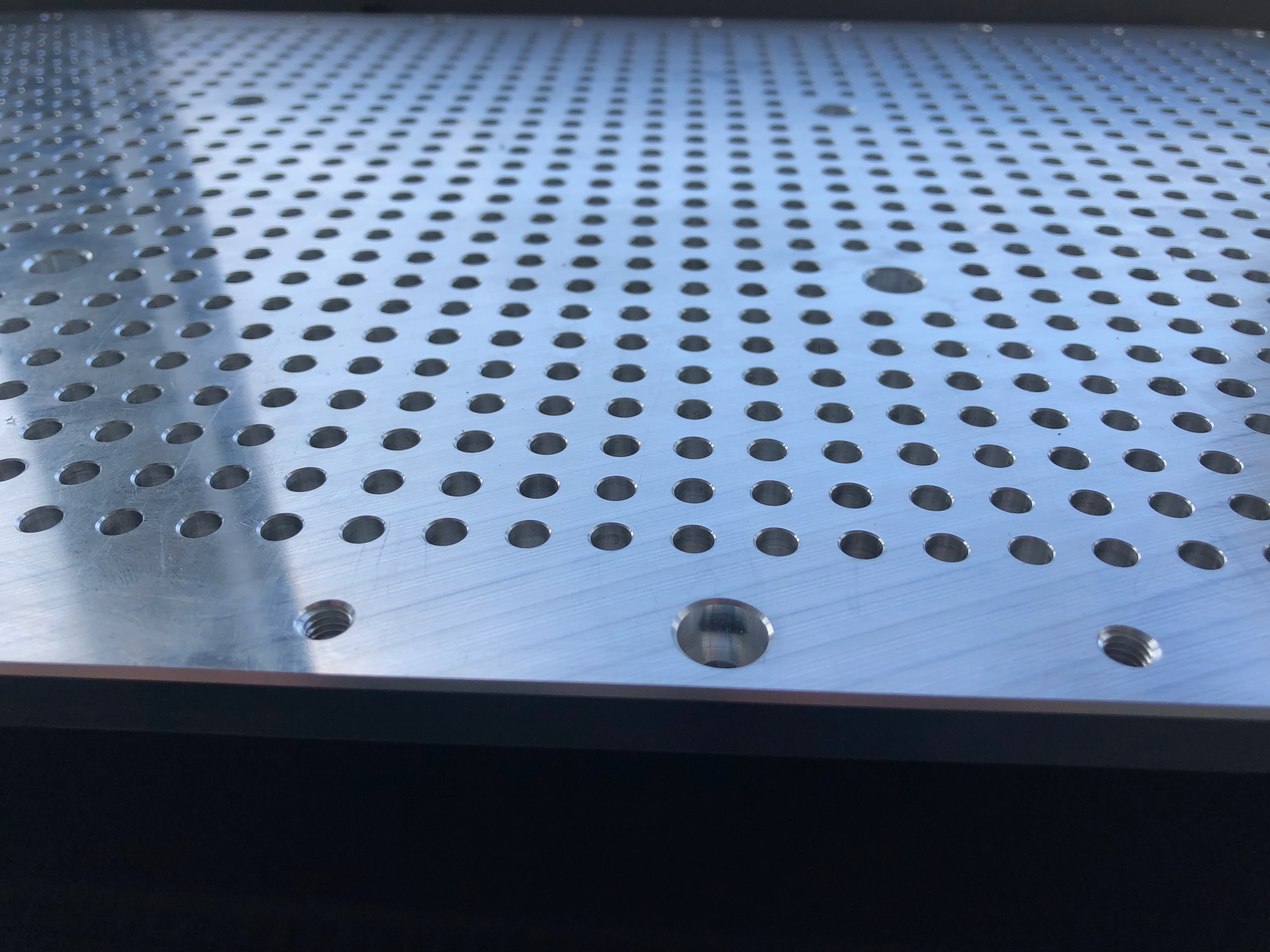
- 10mm distance from hole to hole, so that many commercial rubber mattes will fit (e.g., the matte shown in the video of END CNC)
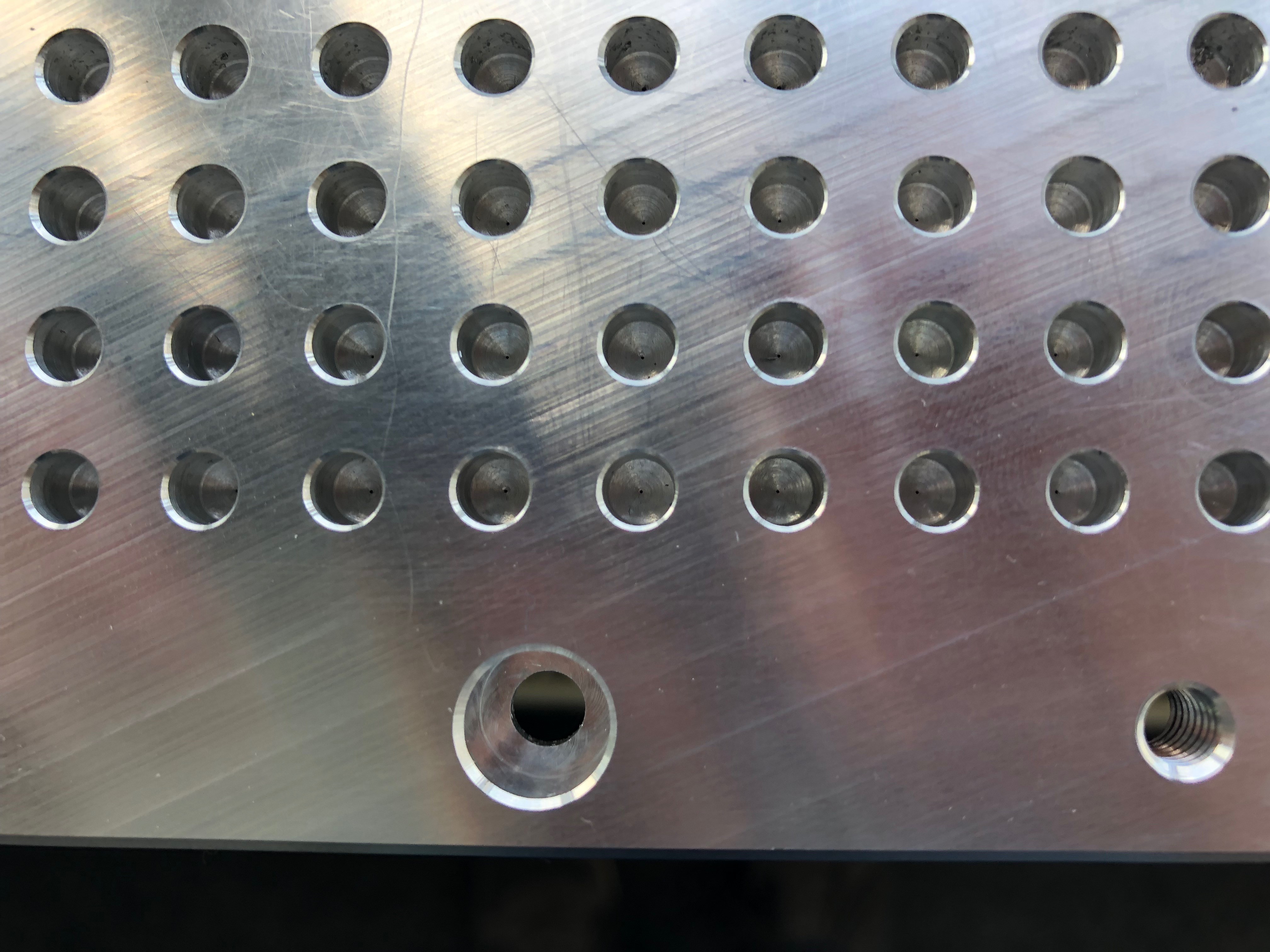
- 5mm diameter of the holes, but just 0.2mm to supply the vacuum to the parts
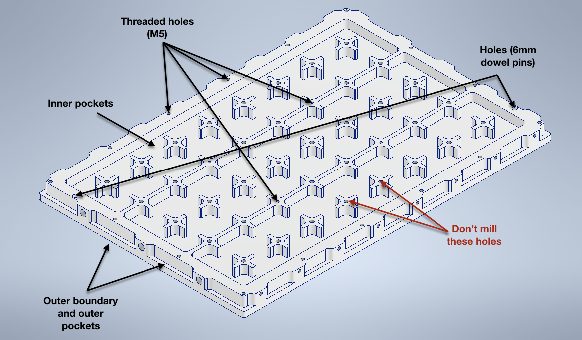
- Holes with M6 threads to clamp stuff onto the vacuum table
- Three vacuum chambers
- Possibilities to add end stops to three of the four sides
- About 4 mm additional thickness to be used to plan the surface if required
The current CAD model consists of two main aluminum parts, some sealing mass, pneumatic connectors and some screws. That's it.
To use the table, some other parts are required. At least one vacuum pump, some tubes, mattes with 5mm holes (10 x 10 raster) and some mattes to close the remaining holes of the table.
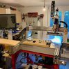
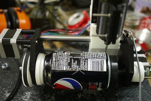
There is a video series on Youtube where the parts are machined and assembled. The videos are linked below.

 Quinn
Quinn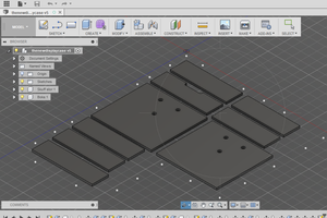
 Øystein
Thank you for this great project. Today I started with the bottom plate (900x700x20mm). I‘m using M6-steel inserts for future fixing and changed your design for my needs. I‘m also from Germany…