 Dan Julio
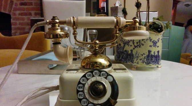
Bluetooth to POTS phone adapters have been done many times before. I first saw the idea in Sparkfun's Port-O-Rotary and over the years in several projects documented here and described on HaD. My partner has kept several old phones displayed even as we removed landline support and went, as most everyone has, to cellphones and voip services. Like a lot of people I think the old phones are cool and wanted to make them work again without modifying them at all. I found a couple of existing products like the cell2jack and HiQ Landline to Bluetooth adapter but decided I wanted to learn about how POTS service worked and built my own. That way I could have exactly the features we wanted and I could share the design so others could build them too.
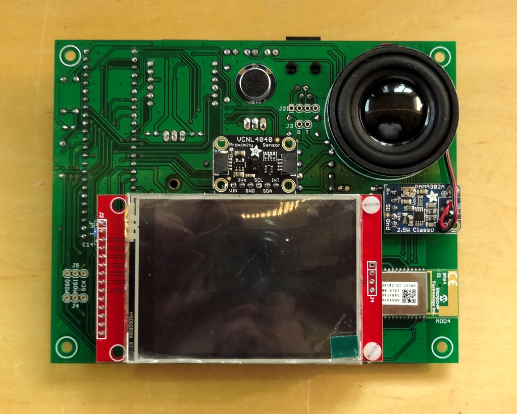
The goal of Blue POT was to provide a real old-school telephone experience. Phones had to ring when a call was received. The right tones had to be generated in the receiver and both DTMF and rotary dialing had to be supported. Although the Bluetooth interface proved to be a bigger pain in the end I initially focussed on how to generate the voltages necessary to run and ring a set of phones connected via existing house wiring and dealing with decoding dialing information. I spent quite a bit of time contemplating how to drive the phone line until I found the most amazing AG1171.
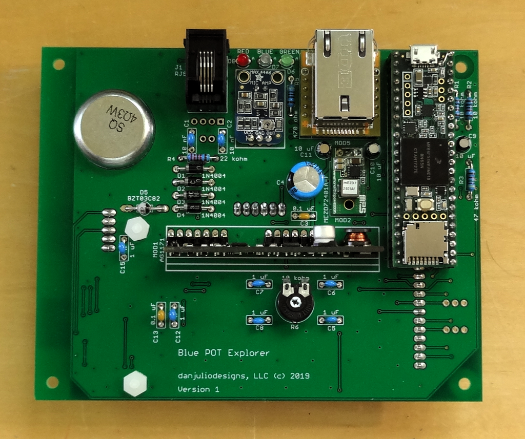
Blue POT is based on three main subsystems.
- Microchip BM64 Module providing Bluetooth Handsfree (HF) / Headset (HS) support. Available at Mouser.
- Silvertel AG1171 SLIC (Subscriber Line Interface Circuit) providing bias and ring voltages, hook detection and audio interface to the telephone line. Available at Symmetry Electronics.
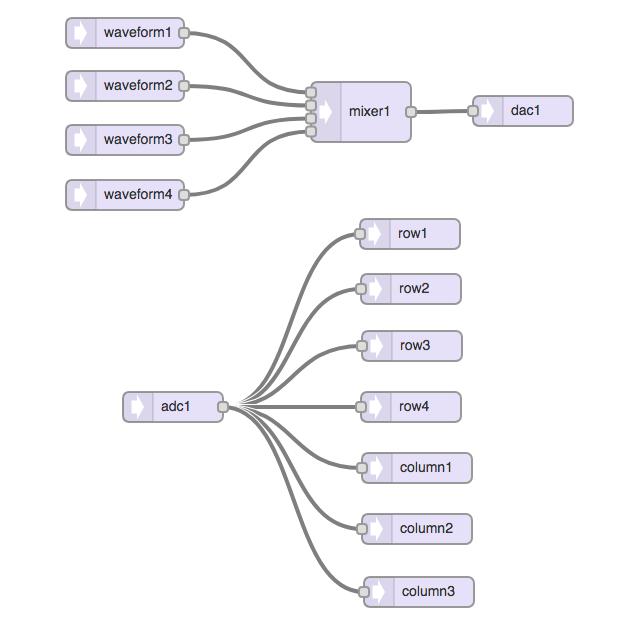
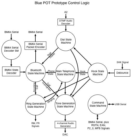
- PJRC Teensy 3.2 controller providing system control, DTMF and Rotary dialing decoding and telephone tone (dial-tone, busy and reciever off-hook) generation. Code is developed and loaded using the Arduino environment with the PJRC Teensy extensions (including the Audio Library used for tone generation and DTMF decoding)


 William
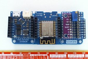

 Anith
Anith
Friggen so cool!