 ensafatef
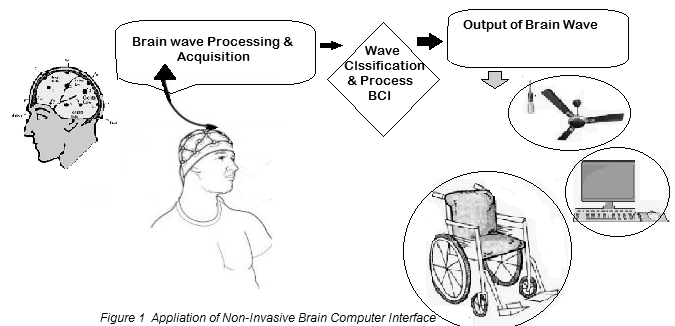
Abstract: Neuroscience is being widely explored to develop more interactive brain computer interfaces for control applications. The objective is to enable a computer to read and display thoughts of a human using an Electroencephalography (EEG) device which is a non-invasive method to record electrical activity of the brain along the scalp [24]. A normal human tends to generate specific electrical signals for each thought. With the use of an EEG sensor we will be able to read the electrical signals generated from the human brain. BCI system consists of Biosensor to capture the EEG/EMG signals. The signals will be processed by the computer program [13]. The Level Analyzer Technique (www.ssla.co.uk) is performed on all the training signals and Alpha and Beta waves are extracted for controlling the Hardwires. The command signals are transmitted to the Microprocessor via RF medium [23]. The robotic module designed consists of ARM Microprocessor [10,11] coupled with DC motor to perform the command. The Eye blinking strength and attention level were used to control the direction of the wheelchair [3]. The wireless BCI system could allow the paralyzed people to control their wheelchair without any complexity, provided it is more enhanced, portable and wearable. The results demonstrate the feasibility of cognitive control network to translate deliberate intentions into commands via EEG based BCI for rehabilitation of physically challenged patients [27].
- 1.Introduction With several developments in the areas of information technology and neurosciences, there has been a surge of interest in turning dreams into reality. The crux of BCI research is to develop a system that allows disabled
people to communicate with other persons and contributes to interaction with the external environments. The electroencephalographic (EEG) devices mostly measure fundamental human activity states as attention, relaxation, meditation etc. In this devices also an electromyography sensor that can be used for eye blinks recognition [8].
- 2. Related Work
The research in the field of brain computer interface began in 1970’s. BCI research and development has focused primarily on neuroprosthetics applications that aim at restoring damaged hearing, sight and movement [1]. The four major phases in BCI systems are data acquisition, signal processing classification, computer interfacing application.The EEG classification was used for control of application software on computers as far back as 1991 [2]. They successfully created a system that allowed a user to control a cursor using EEG signals. Later, Wolpaw explored the area and published his work in a series of papers describing the state of the art throughout the early 2000s [3]. These works were further carried forward in [8], where a large, high resolution EEG was used to control a robotic arm. These studies highlighted the importance of EEG, but unfortunately did not address the issues of cost and difficulty of use for the end-user. The need for an easy-to-use and cost effective neuroheadset has been met out by Emotiv EPOC neuroheadset. The Emotiv EPOC has been used in a variety of applications, due to its accessibility for consumers and researchers. The device was validated [1] where it was found to be useful for the control of computers by patients with no voluntary muscle control. These patients were able to access computer based assistive technology and navigate a virtual space using two discrete thought patterns, all with a greater than random chance of success. The Emotiv EPOC was found to be effective methods for computer control, having the subjects of their experiments perform a 3D rotation task in virtual space [9]. The Emotiv EPOC has also been used in the area of controlling robotic systems through noninvasive BCI. In [10] Emotiv EPOC was used to teleoperate a remote humanoid robot. Their system allowed for the remote control of an Aldebaran Robotics Nao humanoid robot, which the user was able to direct with EEG commands to move forward, turn left, and turn right. It was found that their system was effective to navigate a small course. In [11] the Emotiv EPOC was used to control a Lego NXT robot[21].. They used the Emotiv Emokey software to send key commands to a java program. The Emokey software is provided by Emotiv, and allows a user to select different keystrokes to virtually actuate based on EEG data, with up to four outputs being trained [12]. The authors in [13] showed the use of the Emotiv EPOC for the control of robotic arms through EEG. wireless BCI systems may provide a number of advantages. There are still many issues that need to be resolved including improving signal quality, more compact and stylish system designs, and implementation of useful applications [15].
- 3.Objective
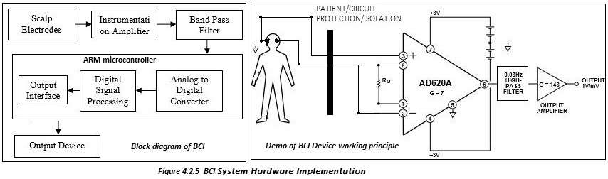
The EEG signals picked up by the electrodes have amplitude of around 5µV to 300µV in the frequency band of 1Hz to 100Hz. The signal picked up by the electrodes is crude due to the interference of noise signals. An active band pass filter of bandwidth 0.1Hz to 100Hz is designed to eliminate signals of other frequencies [21]. The signal also contains 50-60Hz noise due to power line interference which can be reduced by shielding the wires [29]. However, power line interference of ignorable magnitudes can be observed. The signal picked up by the electrode is first amplified by an instrumentation amplifier. Active band pass filter removes the unwanted frequencies from the signal and amplifies it [10]. This analog signal is converted to digital signal using analog to digital converter in the ARM microcontroller and DSP for Computer. Digital signal is processed in the micro controller and accordingly controls the application and appliances [27].
- 4.Research Environment
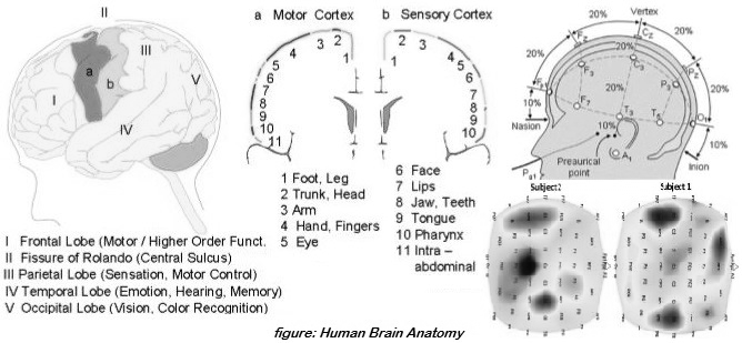
4.1 Human Brain Anatomy
Human brain is one of the most complicated organ that controls the functioning of the whole body.
- Brain Computer Interface Types
Brain computer interface can be classified into three main groups
(i). Invasive BCI: Invasive BCI devices are inserted directly into the human brain by a critical surgery as can be seen in Fig. 2.4. The electro-corticogram (ECoG) are the obtained signals from these inserted electrodes [4]. These devices have the highest quality of human brain signals but have the risk of forming scar tissue.
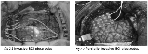
(ii). Partially Invasive: Device inserted in the skull on the top of human brain as depicted in Fig. 2.5. These devices have bit weaker quality of human brain signals than invasive BCIs and have less risk of forming scar tissue [5, 6].
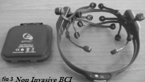
(iii). Non Invasive: Non Invasive BCI devices are considered the safest type and low cost type of devices. These devices have weaker human brain signals than other BCI devices due to the skull [18]. The detection of signals is done by some electrodes placed on the scalp as given in Fig. 2.6. At the same time, placing such electrodes is easy as well as portable. Most noninvasive techniques are constructed by recording ElectroEncephaloGraphs (EEG) from the scalp. Recent EEG Non Invasive BCI devices have better temporal resolution due to use up to 256 electrodes on the whole area of the human scalp. While others, Non Invasive BCI devices, use functional Magneto-Resonance Imaging (fMRI), Positron Electron Tomography (PET), MagnetoEncephaloGraphy (MEG) and Single Photon Emission Computed Tomography (SPECT) [7, 14]
4.2.1 The Instrumentation Amplifier (AD620):
The AD620 is a low cost, high accuracy instrumentation amplifier that requires only one external resistor to set gains of 1 to 10,000. Furthermore, the AD620 features 8-lead SOIC and DIP packaging that is smaller than discrete designs and offers lower power (only 1.3 mA max supply current), making it a good fit for battery-powered, portable (or remote) applications. The AD620, with its high accuracy of 40 ppm maximum nonlinearity, low offset voltage of 50 μV max, and offset drift of 0.6 μV/°C max, is ideal for use in precision data acquisition systems, such as weigh scales and transducer interfaces. Furthermore, the low noise, low input bias current, and low power of the AD620 make it well suited for medical applications, such as ECG and noninvasive blood pressure monitors [28]. The low input bias current of 1.0 nA max is made possible with the use of Superϐeta processing in the input stage. The AD620 works well as a preamplifier due to its low input voltage noise of 9 nV/√Hz at 1 kHz, 0.28 μV p-p in the 0.1 Hz to 10 Hz band, and 0.1 pA/√Hz input current noise. Also, the AD620 is well suited for multiplexed applications with its settling time of 15 μs to 0.01%, and its cost is low enough to enable designs with one in-amp per channel.
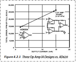
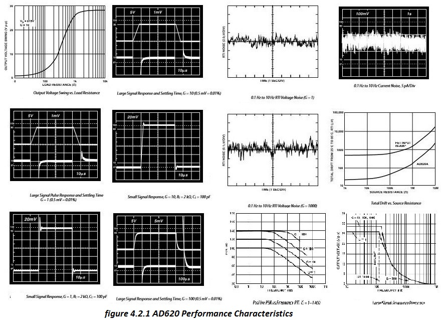
AD620 Performance Characteristics:
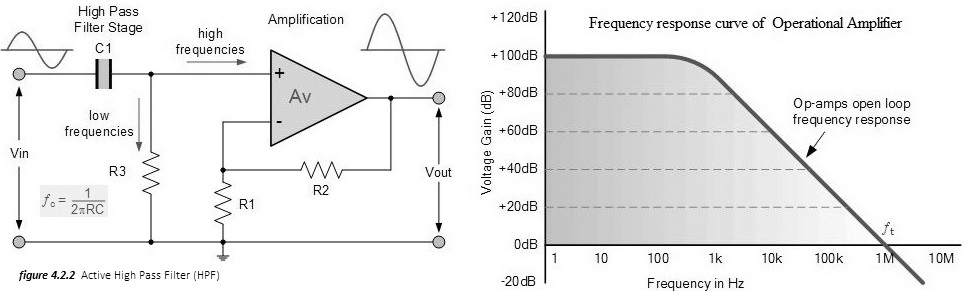
The basic operation of an Active High Pass Filter (HPF) is same as for its equivalent RC passive high pass filter circuit, except this time the circuit has an operational amplifier or included within its design providing amplification and gain control.
Voltage Gain (Av):
Vout / Vin = AF (f/fc) / √1+(f/fc)2
[AF = the Pass band Gain of the filter, (1 + R2/R1), ƒ = the Frequency of the Input Signal in Hertz, (Hz),
ƒc = the Cut-off Frequency in Hertz, (Hz)]
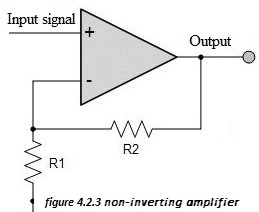
4.3.3 Non-Inverting Amplifier
The signal is applied to the non-inverting input of the amplifier. The feedback is taken from the output via a resistor to the inverting input of the operational amplifier where another resistor is taken to ground. It is the value of these two resistors that govern the gain of the operational amplifier circuit.
As the input to the op-amp draws no current this means that the current flowing in the resistors R1 and R2 is the same. The voltage at the inverting input is formed from a potential divider consisting of R1 and R2, and as the voltage at both inputs is the same, the voltage at the inverting input must be the same as that at the non-inverting input. This means that Vin = Vout x R1 / (R1 + R2). Hence the voltage gain of the circuit Av can be taken as: Vout / Vin= Av = 1 + R2/R1
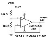
4.2.4 Reference Voltage Line
The circuit is powered by single supply voltage of 5V. If the output of instrumentation amplifier of operational amplifier is negative, it is observed as 0V as there is no negative supply to amplifiers. Using a reference voltage of 2.5V, the output is added with DC Offset of 2.5V. The signal above 2.5 volts is positive and signal below 2.5V is negative.
4.2.5 Hardware Component:
The iSCADA (www.ssla.co.uk/product/iot-evaluation) unit in the brain of the system. It is an Open-source physical computing environment based on a simple I/O board used to develop stand-alone interactive objects or it can be connected to a software on your computer [26]. Basic filtering uses instrumentation amplifier, notch filters, high pass filters and low pass filters for filtering artifacts and noise [22]. It takes input from EEG sensor, heartbeat sensor, eye blink sensor and temperature sensor. After the amplification and the filtering, the microcontroller will process the signals and give the output according to the specific algorithm. The microcontroller will do the following operations: 1. Will take the digital signal data from the ADC and process it according to the working specified [22] 2. The microcontroller will be directly connected to the user interface which will display the data selected [8], and details such as concentration level of raw data on DSP application. 3. The microcontroller will send the processed data wireless help of Wi-Fi or Bluetooth module to action process server. BCI Hardware Implementation Demo:
All the hardware of brain computing interface hardware symmetric and software blueprint are given in Github link bellow
https//github.com/Rhythmkrdasgupta/BCI
4.2.6 BCI Signal Features Analysi
User must be able to control the output: Use a feature of the continuous EEG output that the user can reliably modify (waves), or Evoke an EEG response with an external stimulus (evoked potential) [30, 18].
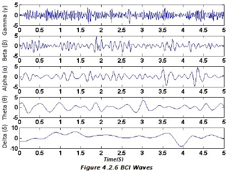
(a) Delta (δ): Delta wave are characteristic of deep sleep and high amplitude frequency range 0 ≤ f ≤ 4 Hz [21].
(b) Theta (θ): Frequency range 4 ≤ f ≤ 8 Hz during meditation, idling or drowsiness. "slow" activity. It is generally present in children up to 13 years and in sleep but abnormal in awake adults.
(c) Alpha (α): Frequency range 8 ≤ f ≤ 14 Hz during relaxing or reflecting. Another way to boost alpha waves is to close the eyes [16].
(d) Beta (β): Frequency range 14 ≤ f ≤ 30 Hz and characteristic are when the user being alert or active and while the user is concentrating.
(e) Gamma (γ): Frequency range 30 ≤ f ≤ 70 Hz or above during the mechanism of consciousness.
4.2.7 Monitoring Brain Activity Using Computer Program:
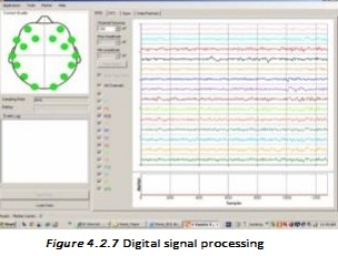
Digital signal processing (DSP) is the use of digital processing, specialized digital signal processor convert the analog signal to digital form, to perform a wide variety of signal processing operations. A Digital Signal Processor (DSP) can process data in real time, making it ideal for applications that can’t tolerate delays [15].DSP applications include audio and speech processing, sonar, radar and other sensor array processing, spectral density estimation, statistical signal processing, digital image processing, signal processing for telecommunications [28], control systems, biomedical engineering, seismology, among others [29]. A digital signal processor is designed to perform these mathematical functions rapidly [12]. The application of digital computation to signal processing allows for many advantages over analog processing in many applications, such as error detection and correction in transmission as well as data compression. DSP is applicable to both streaming data and static (stored) data [22].DSP can involve linear or nonlinear operations. Nonlinear signal processing is closely related to nonlinear system identification and can be implemented in the time, frequency, and spatio-temporal domains.
Here we used DSP filter the brain wave (delta (δ), theta (θ), alpha (α), beta (β), gamma (γ)) signal and process it digital form.
5. Conclusion & Future Enhancement
The project has very important scope in future. The project can be implemented by using EEG headset. With the proposed system of brain computer interface (BCI) for paralyzed or physically challenge people [13]. User can turn on the alarms, control the wheelchair [13], communicate with computer and send message to the caretaker as well as to nearby hospitals [23]. This can be also modified in such a way that a call can also be originated. To make the readings of the brain signals accurate, we can use the 64 or 3 base electrodes that are attached to the brain instead of the 3 electrodes used here [17]. We can also use the EEG sensor to record the accurate reading of the eye blink instead of using separate eye blink sensor [3]. In the same way we can also use EEG to detect the heartbeat of the patient. Better filtering circuits can be also included. We can also use wireless equipment instead of wired equipment’s [18]. Since the GSM is having connectivity problems, we can use other technologies such as Wi-Fi, RF transmitter and Bluetooth [15]. Instead of using separate sensors for monitoring the patient we can take all the readings using EEG.
6.Acknowledgement
This project required genuinely efforts. Nevertheless, it would not have been realizable without the assistance and help from many individuals and organizations. Various tutorials and resources given in the official website of Open BCI have made initial works easier.
Finally, my thanks and appreciations SSLA.CO.UK who have willingly helped me out with their abilities.