 Corey Benn
The basic BOM
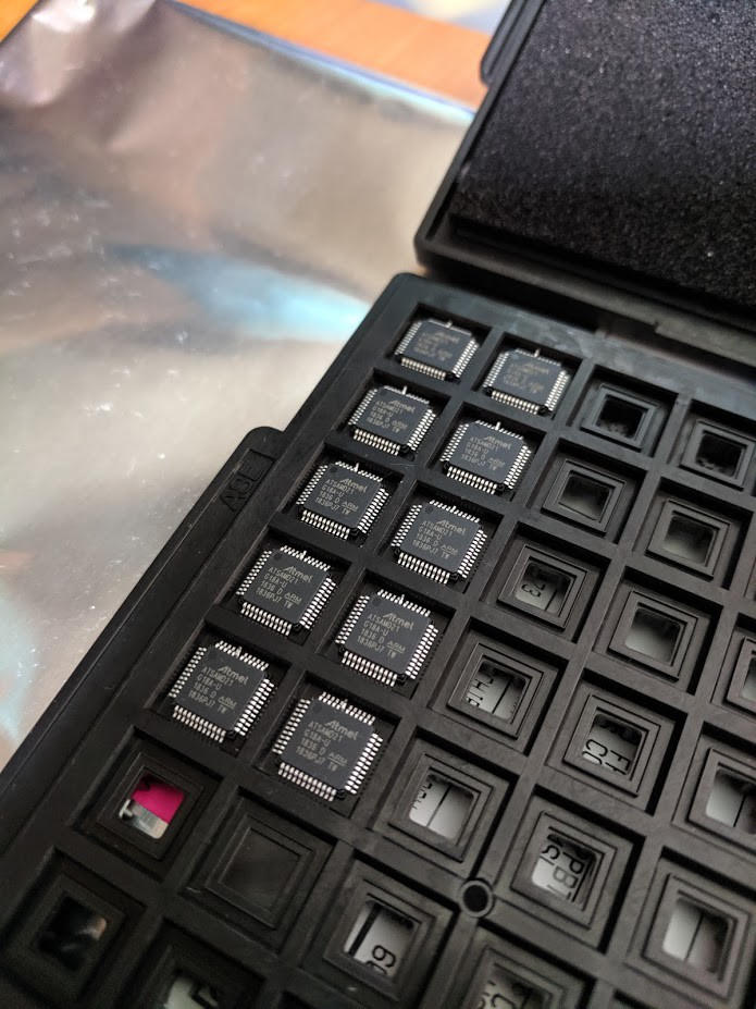
- (1) ATSAMD21G18A
- (4) 2x3 Female PIN Headers (Keyed preferred)
- (12) SUNLED LED 2PLCC SMD (XZM2CYK45WT)
- (6) BC817 NPN Transistor
- (1) Micro-USB 10118194-0001LF
- (1) Polulo 3.3V Step-Up Voltage Regulator U1V11F3
- (1) PhotoResistor
- (2) AA Batteries

 blinkingthing
 deʃhipu
 Christian Walther