0%
0%
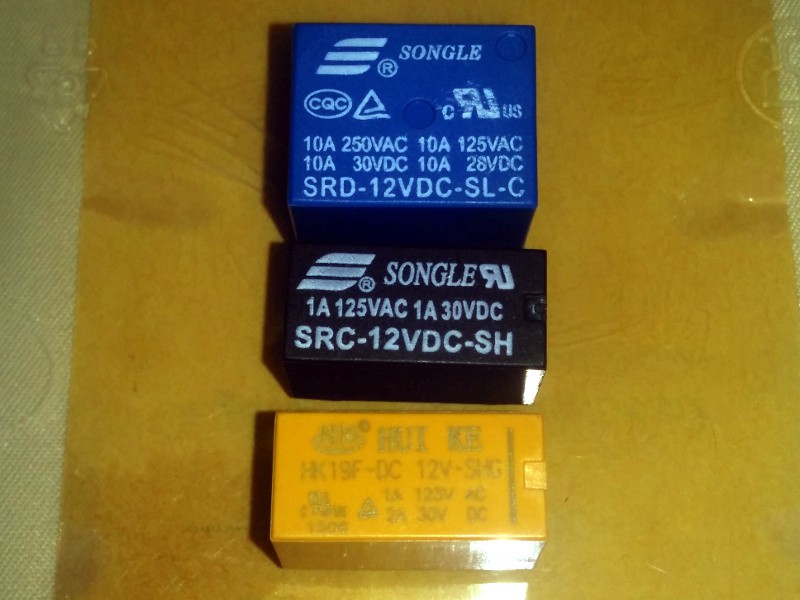
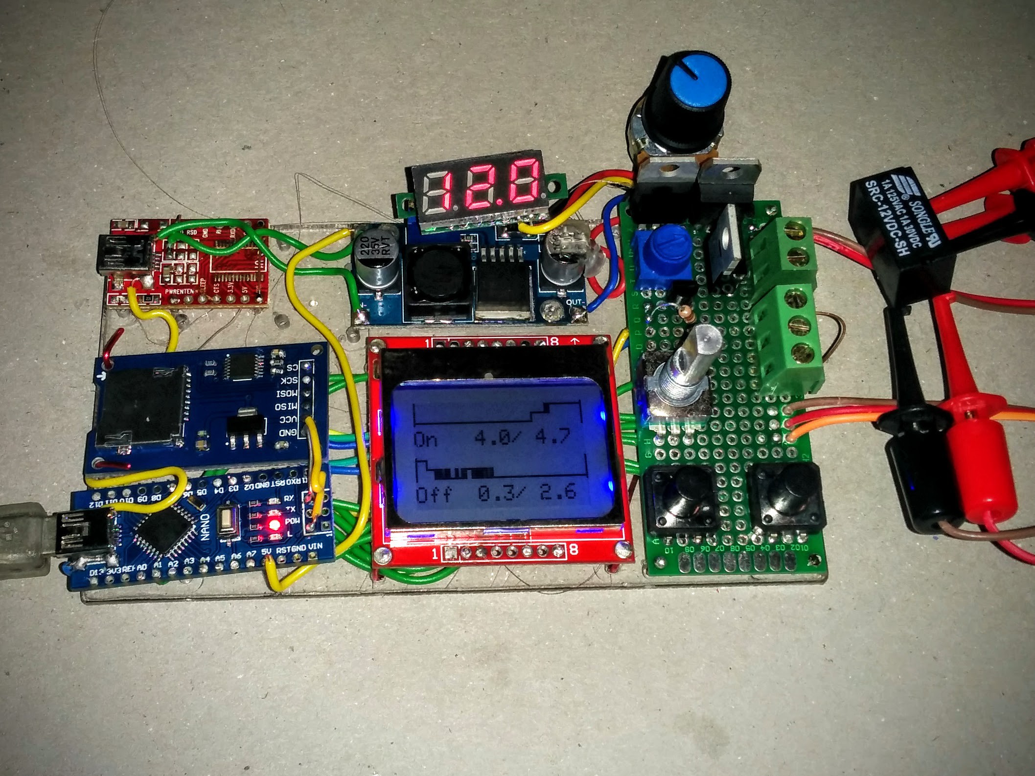
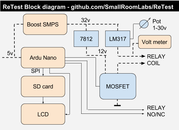
ReTest - Relay timing tester
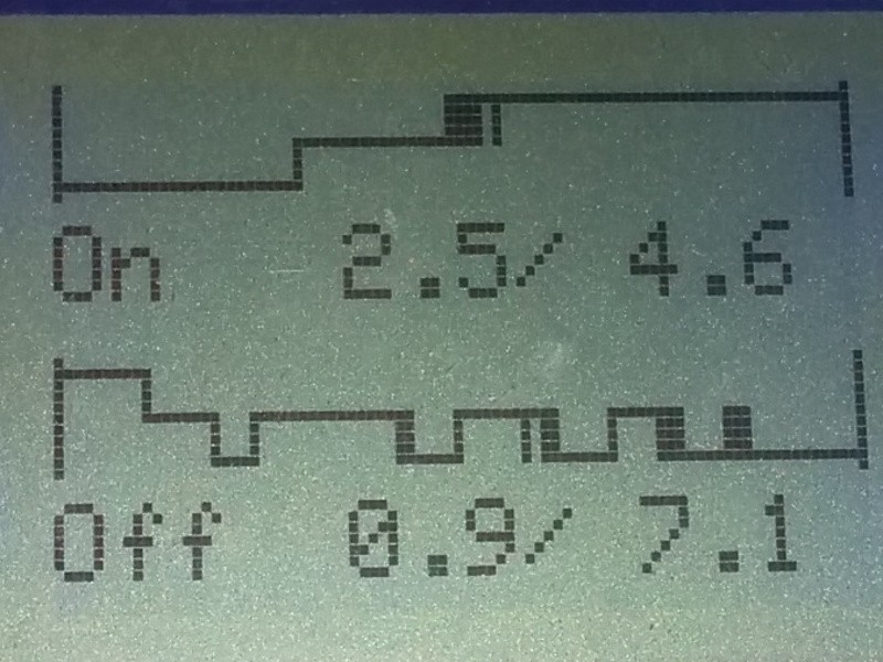
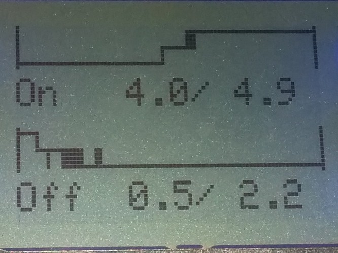
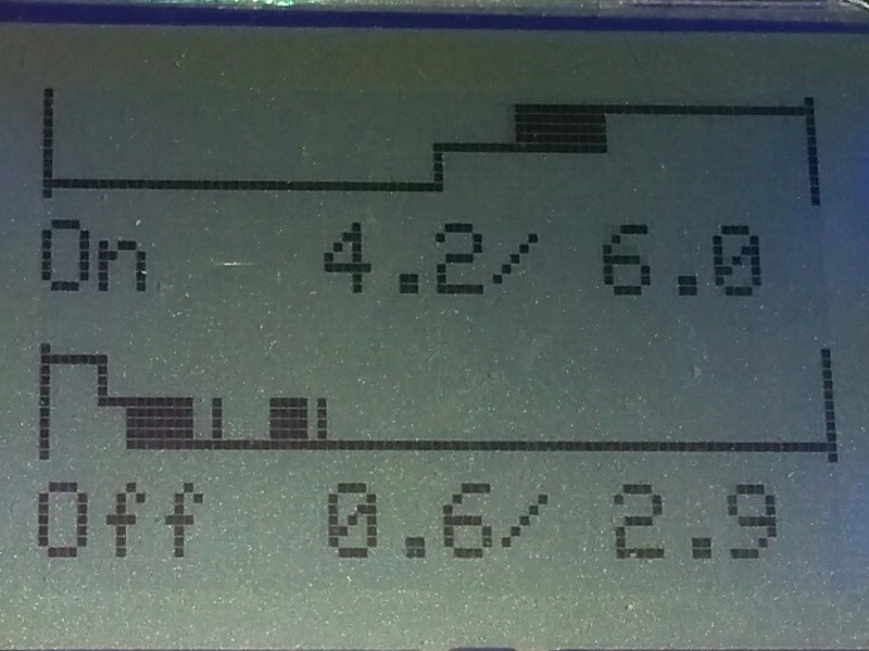
Characterise relay performance data as a one-shot or over millions of operations.
 matseng
Become a Hackaday.io member
Already have an account? Log in.
Just one more thing
To make the experience fit your profile, pick a username and tell us what interests you.
Pick an awesome username
hackaday.io/
Your profile's URL: hackaday.io/username. Max 25 alphanumeric characters.
Pick a few interests
Projects that share your interests
People that share your interests


 Johnny
 Chris B
 JF
JF
 Yann Guidon / YGDES
So, I've been looking into relays for some unrelated project (although I suffer the same ailment as many here, having collected boxes, bins and reels of surplus relays for an eventual clock and/or computer). One of the things I can't get my head around is dry vs wet switching (in other words switching with voltage across the contacts or not). Evidently, for some contact materials/designs, you need to switch current to break through oxide layers on the contacts. Switching zero current can result in high contact resistance, or no contact at all in some circumstances.
The old way around this issue was to get mercury-wetted contacts, but those are long gone (thanks RoHS!) I guess some expensive contact materials can be switched dry, and for some reason reed relays seem OK, too, but they are primarily SPST.
I think in any sufficiently complex relay circuit (computer), you'll probably end up with some contacts that get dry-switched in some states, so it might be best to figure out how big a problem it really is.
So, I'm finally getting around to wondering the best way to modify this system to test the real effects of dry switching the contacts. Maybe have the contacts connected to I/O pins which cn be tri-stated to dry-switch the contacts, then drive one pin and detect the voltage on another?
EDIT: I got so pulled in by this project, I forgot to say much I like the idea. Nice work!