 Adam Taylor
Installing DesignStart FPGA
The first thing we need to do is create a DesignStart FPGA account, we can do this here.
Once registered you will receive an email, this email will contain the links to download Xilinx Vivado and crucially request an license key for Arm Keil

Registration Email Links
Clicking on the request key linkk will allow you to receive the Produce Serial Number, which is needed to generate a 90 day Arm Keil Essentials license.
With both Vivado and Arm Keil correctly installed and licensed, the next step is to download the reference M3 design for the Arty A7 which can be obtained here

DesignStart FPGA download
The downloaded Cortex-M3 will be contained within a compressed file, extract the compressed files until you see the following file structure.

File Structure for the extracted design
The next step is to set up Vivado such that we can work successfully with the example. The first step is to open Vivado and correctly set up a drive to enable Vivado to be able to work with the long path names in the directory strucutre.
Open Vivado and prior to opening the project in the TCL window enter the following commands. The installation directory is the path where you extracted the compressed file.
pwd cd <Installation Directory> exec subst V: .
This will map the installation directory to the drive V:\
With that we can open the Vivado project which you will find under
V:\hardware\m3_for_arty_a7\m3_for_arty_a7
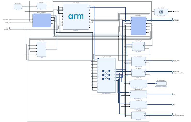
Within Vivado if you open the block diagram you will see the Cortex-M3 block and the supporting IP including AXI GPIO, AXI UartLite, AXI BRAM Controller and AXI QSPI.

Reference Cortex-M3 design in Vivado
Development Flow
To create the Motor control application we need to use the following tools.
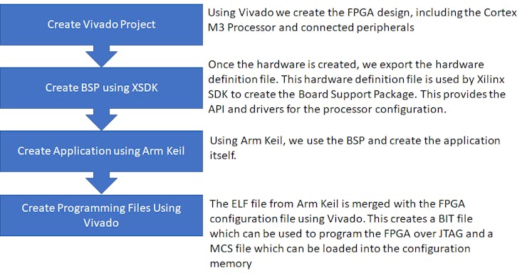
Cortex M3 Development Flow
Memory Map
The memory map of the Cortex-M3 design is as shown below, we will run our application from the ITCM which is the Instruction Tightly Coupled Memory.

Memory Map
Motor Control
This application will drive two wheels to allow the robot to navigate. To do so we need to be able to control the motor.
Unlike our other robotic projects (here and here) we will not be using servo motors but in there place we will be using Brushless DC Motors.
The motors in this application cannot be driven from a 3v3 logic supply like we use with the FPGA instead they will be using a higher voltage (10-12 volts). We will also need to be able to drive the motors in both forward and reverse.
To be able to supply higher voltages and control the direction of voltage flow across the motor we use a H Bridge configuration.
We use one H Bridge for each motor in the design, for this application the PmodHB3 will be used.
The two images below show the circuit diagrams for the PmodHB3 and the direction of voltage flow between the M+ and M- terminals.

H Bridge Voltage Flow for forward Motor Control

H Bridge Voltage Flow for Reverse Motor Control
The PmodHB3 is controlled using two GPIO, one which sets the direction and a enable signal which applies the voltage.
When we are working with this Pmod we must be VERY CAREFUL to ensure we do not change the direction while the enable is asserted. This will lead to creation of a short and has the potential for damage.
Updating the Vivado Design
As we are going to be using Pmods for Motor Control we need to have the Digilent Vivado library mapped in as an IP repository. If you do not have it you can obtain the repository here.
The PmodHB3 uses the PmogGPIO interface standard that is we can use GPIO signals to drive the PmodHB3. There are two signals we need to drive the direction and the enable.
The direction determines the voltage path through the H Bridge, while enable acts as a PWM based signal.

PmodHB3 Architecture.
To dive both motors we are going to need to add in two PmodGPIO IP cores from the Pmod library. We can then port map these on the Arty Pmod Ports A and B.
The design will be updated as shows below

Adding in the PmodGPIO
Once the two PmodGPIO have been added you can run the connection automation to connect them into the system.
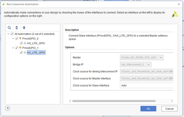
Connection Automation Options
Once both PmodGPIO are mapped into the AXI system we can assign the outputs by double clicking on the PmodGPIO IP block and selecting the correct Pmod position from the drop down menu.

Selecting the correct Pmod
With the PmodGPIO added in the design should look as below.
Completed Design with the PmodHB3 included
To enable us to build this into a wheeled robot we are also going to use a PmodMAXSONAR. This IP can be added from the IP Repository too, we can use this sensor to determine how close we are to objects.
I have assigned the PmodMAXSONAR to the Pmod connector D on the Arty Board. PmodC has a specific use for debugging if we desire.

Block Design With PmodMAXSONAR added in to Pmod JC
When we add in these IP cores ensure the address range is correct, they should be in the 0x40000000 to 0x60000000 range (see memory map above). If new IP added is not in the correct address range we need to manually update the address.
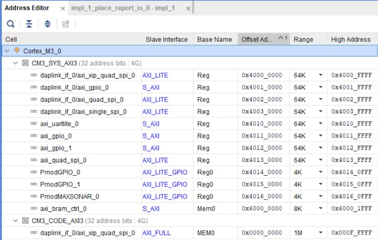
Completed M3 address space
Once the design has completed implementation the next stages are shown below

Updating the design flow
You can find the make mmi_script in the
V:\hardware\m3_for_arty_a7\m3_for_arty_a7
Directory, to run the file use the Vivado TCL console as shown below

Updating the MMI File with the implemented design open
Once the MMI file is up to date the next step is to export the hardware and update the BSP in XSDK.
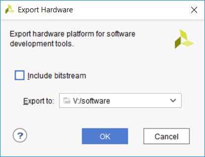
Exporting the updated HW design
When we export the hardware design there is no need to include the bitstream, as we will be using Vivado to update the bitstream later.
If you have XSDK open you should see a warning about the updated hardware definition
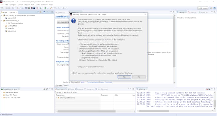
Warning about Hardware Definition being Updated
Click on yes so the hardware definition and BSP can be updated.
When this has finished under the BSP you will see the PmodGPIO drivers also included under the BSP Libsrc directory

Updated BSP with the PmodGPIO
Writing the Software
The software development will build upon the existing design provided with the DesignStart FPGA Cortex-M3 Example.
Once the BSP is updated, we can develop the application within Arm Keil. The first step is to pull in all of the new Pmod drivers. To do this we right click on the project and select Manage Project Items.

Opening the Project Items to Manage.
This will open a dialog, we need to add in the PmodGPIO and PmodMAXSONAR, we do this by selecting New and the entering a name.

Creating a new group
Once the group has been created the next stage is to import the source code and header files.

Importing the source code and drivers
Writing the code is then straight forward, we can use the following functions from the Pmod drivers to control the motors and read the sonar distance.
GPIO_begin(instance,base address,default value); MAXSONAR_begin(instance, base address, clock frequency); GPIO_setPin(instance, pin, value); // sets the pin and direction dist = MAXSONAR_getDistance(instance); // reads the distance
Of course we need to be able to time events in our application as such we will be using the Cortex M3 system tick timer.
This will generate an interrupt at a pre-determined interval, we can use this to time events such as sampling the distance.
//defining the timer   #define STCTRL      (*( ( volatile unsigned long *) 0xE000E010 ))
#define STRELOAD    (*( ( volatile unsigned long *) 0xE000E014 ))
#define STCURR      (*( ( volatile unsigned long *) 0xE000E018 ))  #define SBIT_ENABLE     0
#define SBIT_TICKINT    1
#define SBIT_CLKSOURCE  2
#define RELOAD_VALUE  99999   STRELOAD = RELOAD_VALUE;  STCTRL = (1<<SBIT_ENABLE) | (1<<SBIT_TICKINT) | (1<<SBIT_CLKSOURCE);
To test this was working correctly I initially set up the ISR to print to the terminal when a tick occurred.
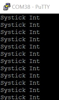
System Tick Running
Now we are happy the system timer is working we can use it sequence actions in our design.
As we can control the time between interrupts we use the following equation to set the reload value
(CLK_Frequency - Ticks per second required) - 1
In this example the Cortex M3 is clocked at 50 MHz.
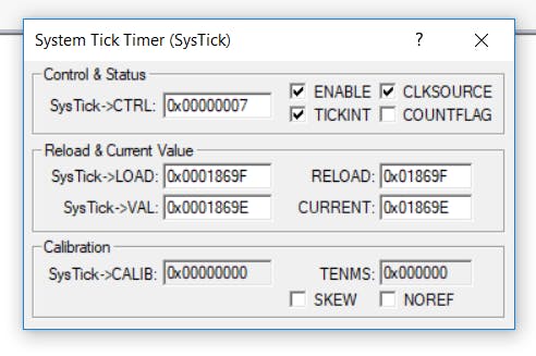
System Tick Viewer in Debug view (J-LINK or Arm DAP required)
With the timer working correctly the PmodMAXSONAR sensor was reporting accurate distances when tested.
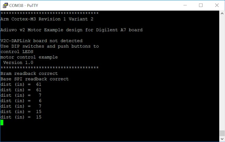
PmodMAXSONAR Output
Running the Code
Once we have written the code the next step is to download it into the arty board.
When we build the code in the Arm Keil, a hex and elf file are created and copied into the hardware project directory.
Within this directory there is a batch script which will take these files and create a updated FPGA bit file which can be directly downloaded into the FPGA. The script will also produce a MCS file which is used for programming the Flash memory on the board such that the application is live at power up
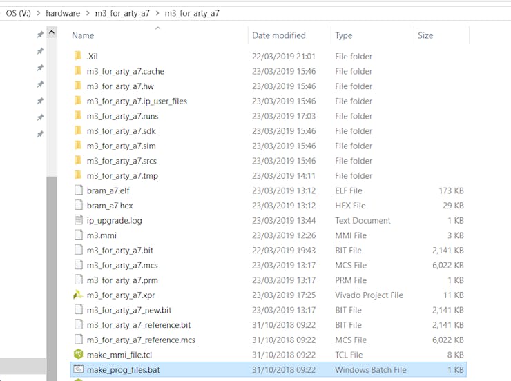
Directory with the batch file and the ELF and Hex files present
Before you generate the updated files make sure the timestamps on the elf and hex have been updated.

The batch file running
We can then use hardware manager in Vivado to download the new FPGA bit stream the application will then start running instantly.

Hardware manager
Select the newly generated FPGA bit file and the image will download into the FPGA.
If you are connected over a USB serial link to the Arty board you will see the following message pop up
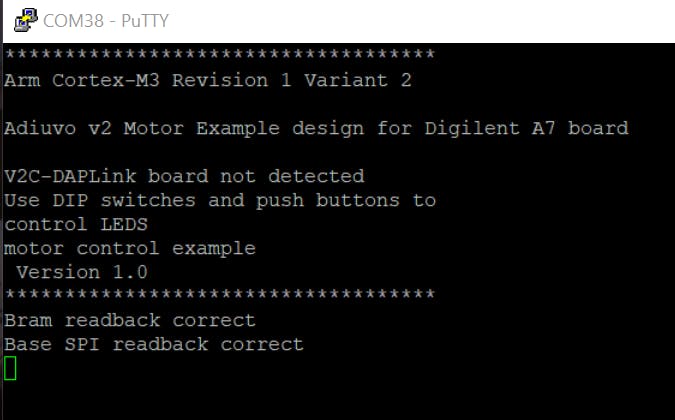
Application starting following download of updated bit stream
For most of our development it is this approach we use to deploy and test our builds.
Although if you have a DAP Link board or Segger J-Link you can check out the debugging section below which maybe of interest.
Initial Motor Test
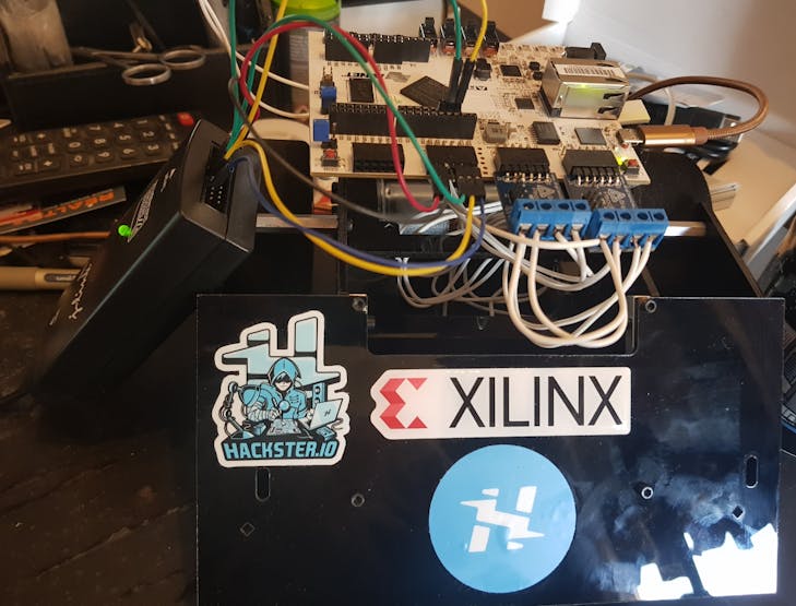
When I tested the initial motor driving code before I build the Robot Chassis, the H bridge was controlling the motor successfully.
Advanced Testing
Once the basics where all in place I implemented a couple of simple functions that would allow the robot to drive forward, reverse, turn left and right.
In the example video below the wheels are moving forward unless the sonar detects a distance of less than 10 Inches in which case the robot stops.
Debugging
The following is optional, but if you decide you want to work further with the Cortex M3 and make modifications to this project you may run into needing to debug your application.
There are two ways to do this, using the Arm DAP link board or we can use a JTAG debugger such as a Segger J-Link.
As I happen to have a Segger J-Link in my lab this was the approach I undertook, it is a little more in depth than using a DAP Link.
Of course, we do not need this as the initial program is downloaded in the bitstream which is loaded over the USB-JTAG link. We just cannot debug the M3 Core that way yet!
The JTAG pins are broken out on the Arty board to both PmodC and the Shield Connector.
The pins are
- TMS - Shield IO-40
- TCL - Shield IO-41
- nTRST - PmodC Pin 1
- TDI - PmodC Pin 2
- TDO - PmodC Pin 3
The pin out on the Segger J-Link is as below, we can use jumper cables to connect between the J-Link and the Arty A7.

SEGGER J-Link Pin out
The connections between the J-Link and the Arty can be seen as below, you should also connect the J-link to GND and VTref to the PmodC power pin.
J-LInk Arty Connections
To use the J-Link within Arm Keil we need to configure the target options as below, we can do this by right clicking on the top level of the project and selecting options for Target 'm3_for_arty_a7'

Opening the Options
This will open a dialog box, as I do not want to download to Flash, just debug. I configured my options as below.

Configuration of the Debug Tab
Select J-Link and click on the settings button

Configuration of the Debug Settings
Click on the Flash download and configure as below

Flash Configuration
Once this is completed we can start a debug session, by selecting the start/stop debug session under the debug menu.

This will download the image and stop the program ready for execution. We can add breakpoints and single step etc just as we can with any other debuggers.
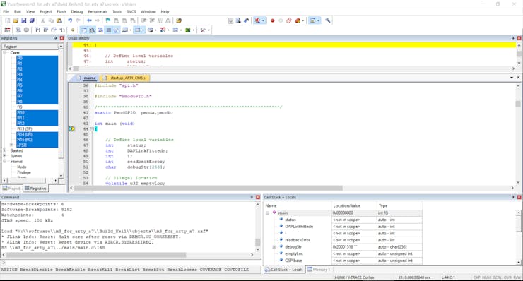
Debugger stopping at program entry
We can set breakpoints by double clicking on the left hand margin, the program can then execute until the breakpoint is hit.
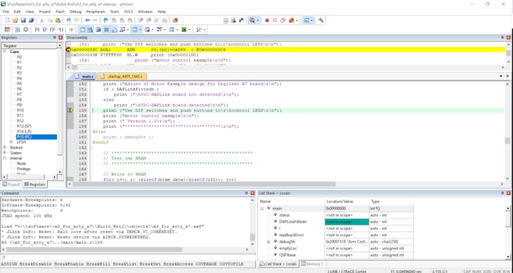
Hitting a Breakpoint
NOTE before you can connect to the Arm Cortex-M3 the FPGA must be configured with one. Arm Keil does not download the bitstream configuration.
Conclusion
Now we have a simple motor control robotic example which can be further developed using the Arm Cortex-M3 from DesignStart FPGA.
Hopefully this project has also shown you how to work and develop your own DesignStart FPGA solutions. It is probably the longest project I have written to date!