Close
0%
0%

If ( ) Then {Paint}

a machine to create canvas paintings of your favorite digital images

Similar projects worth following
A cnc painting system that artists, crafters, and makers can use to create canvas paintings of their favorite digital images cheaper and faster than ever before.

Simply upload an image, define the painting parameters, load the raw materials, and watch the machine create your custom painting.

A cnc painting system that artists, crafters, and makers can use to create canvas paintings of their favorite digital images.

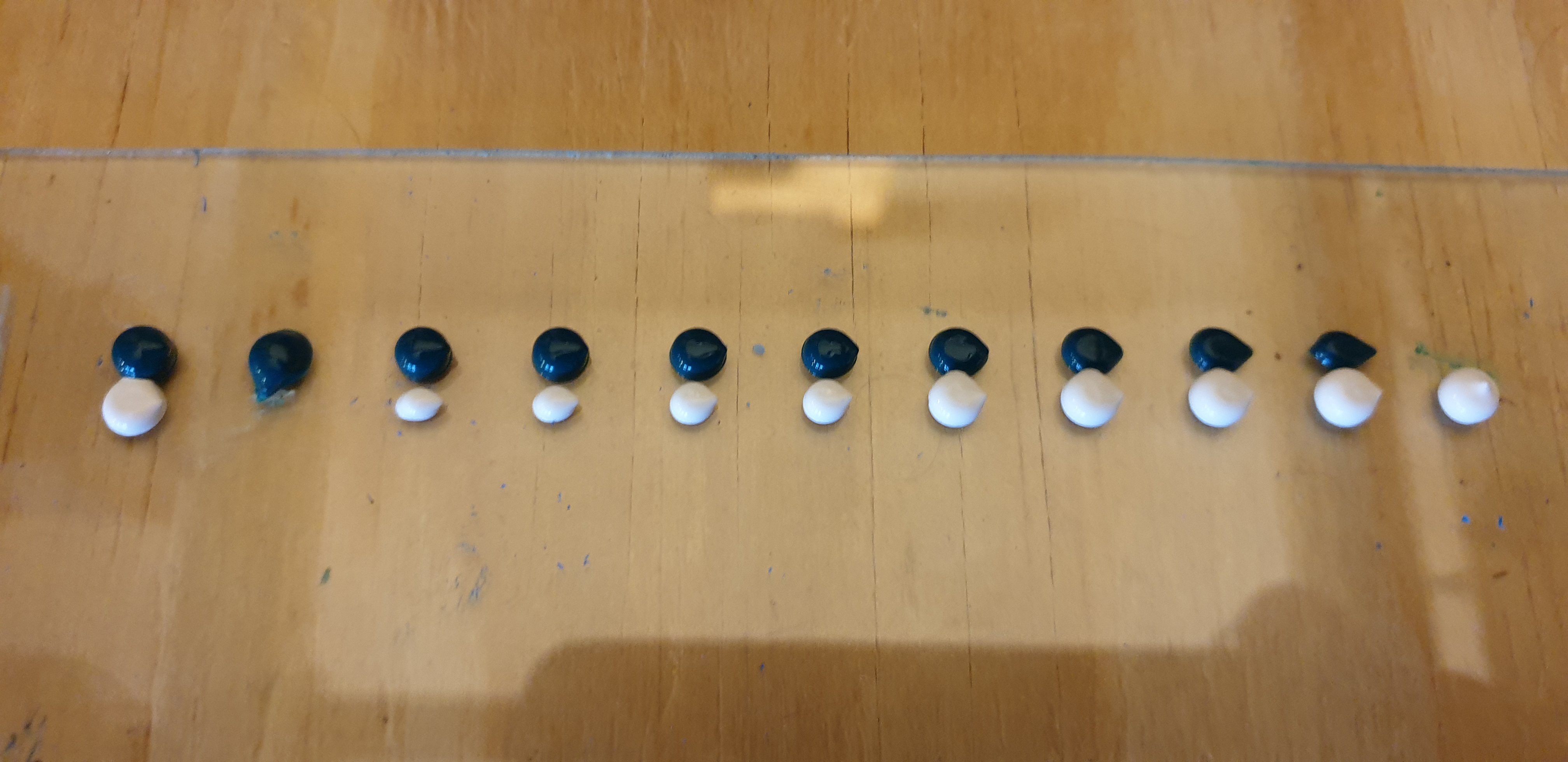
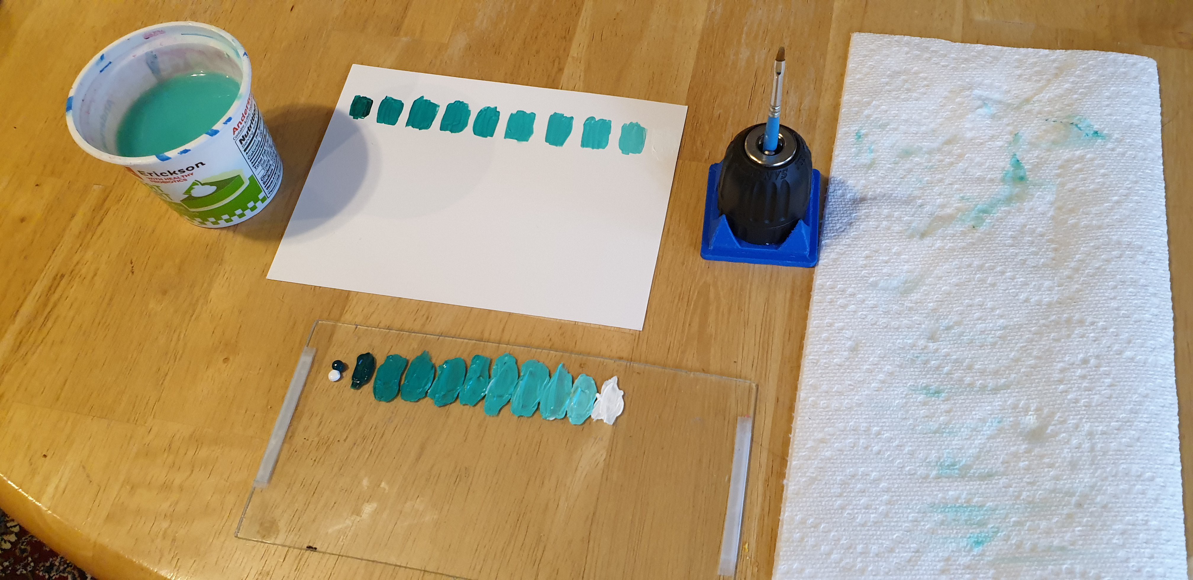
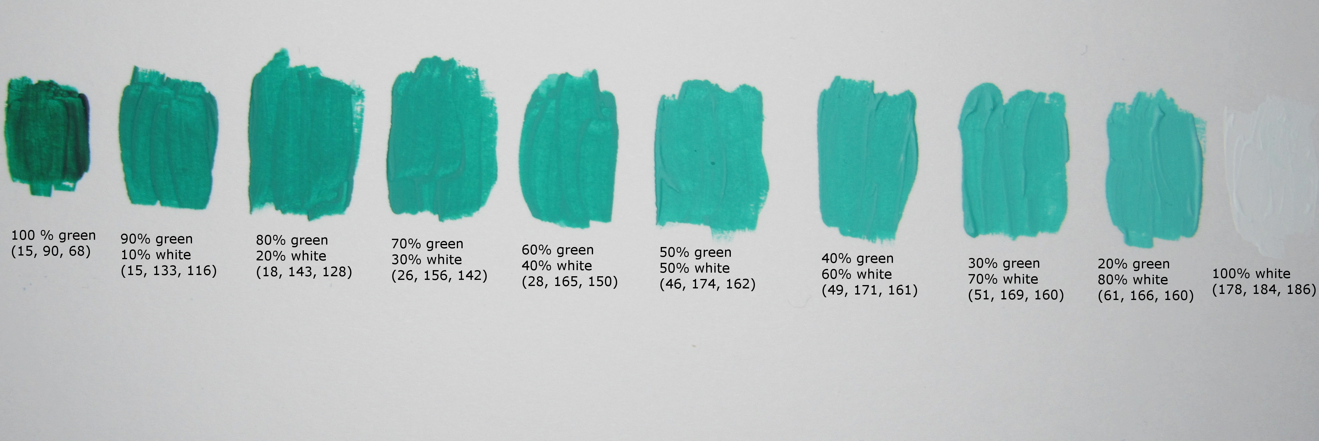
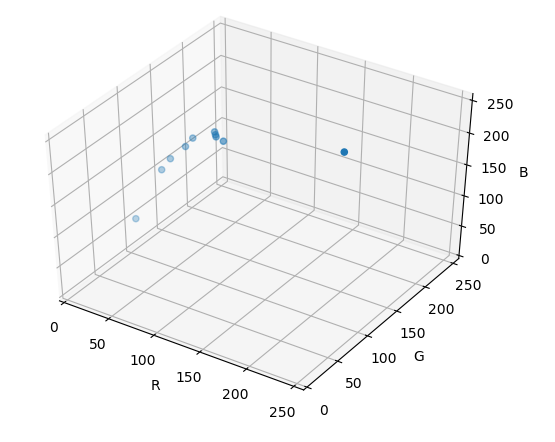
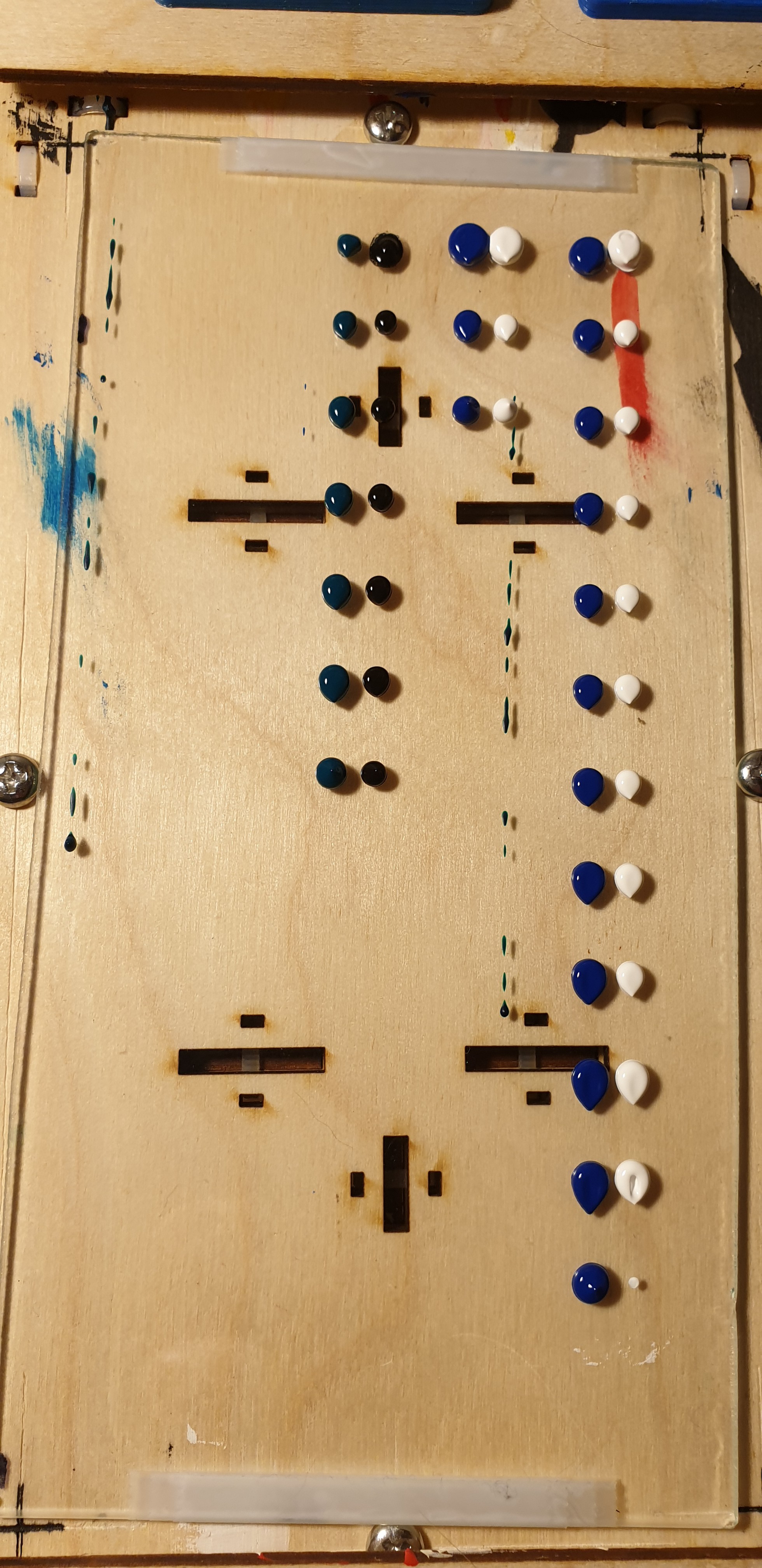
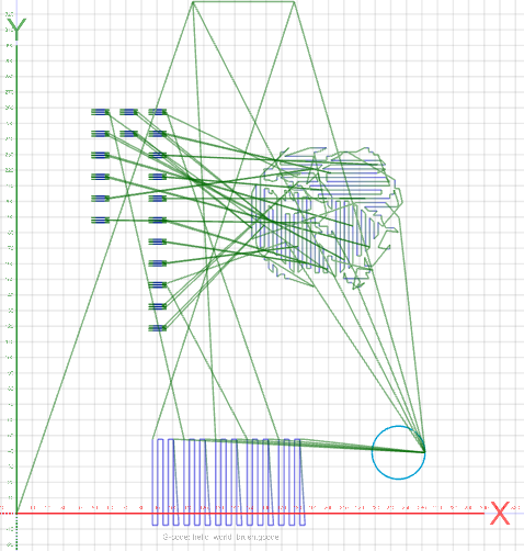
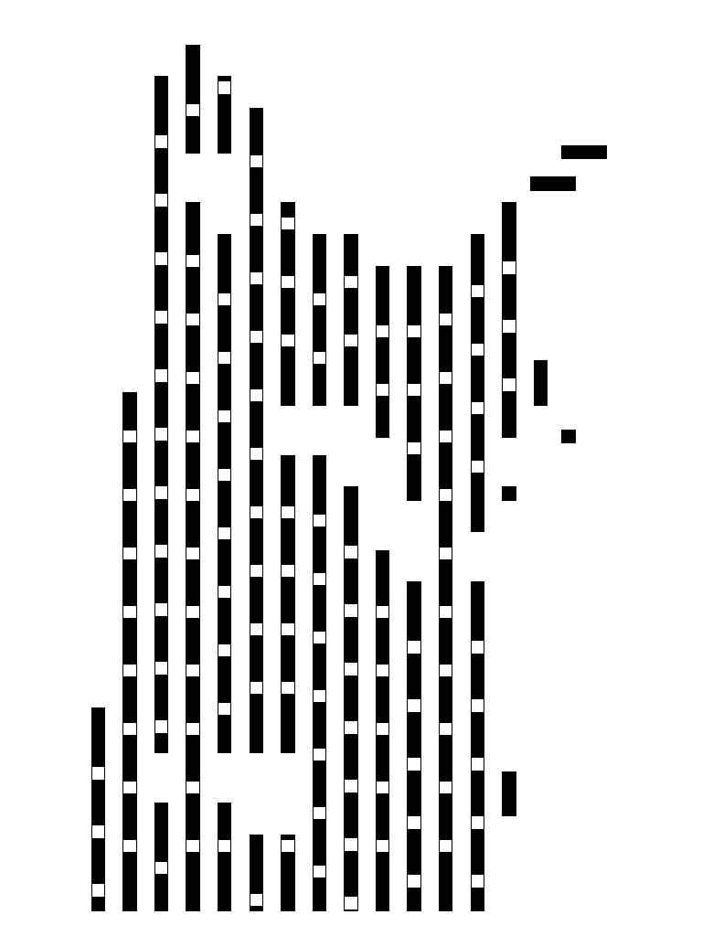
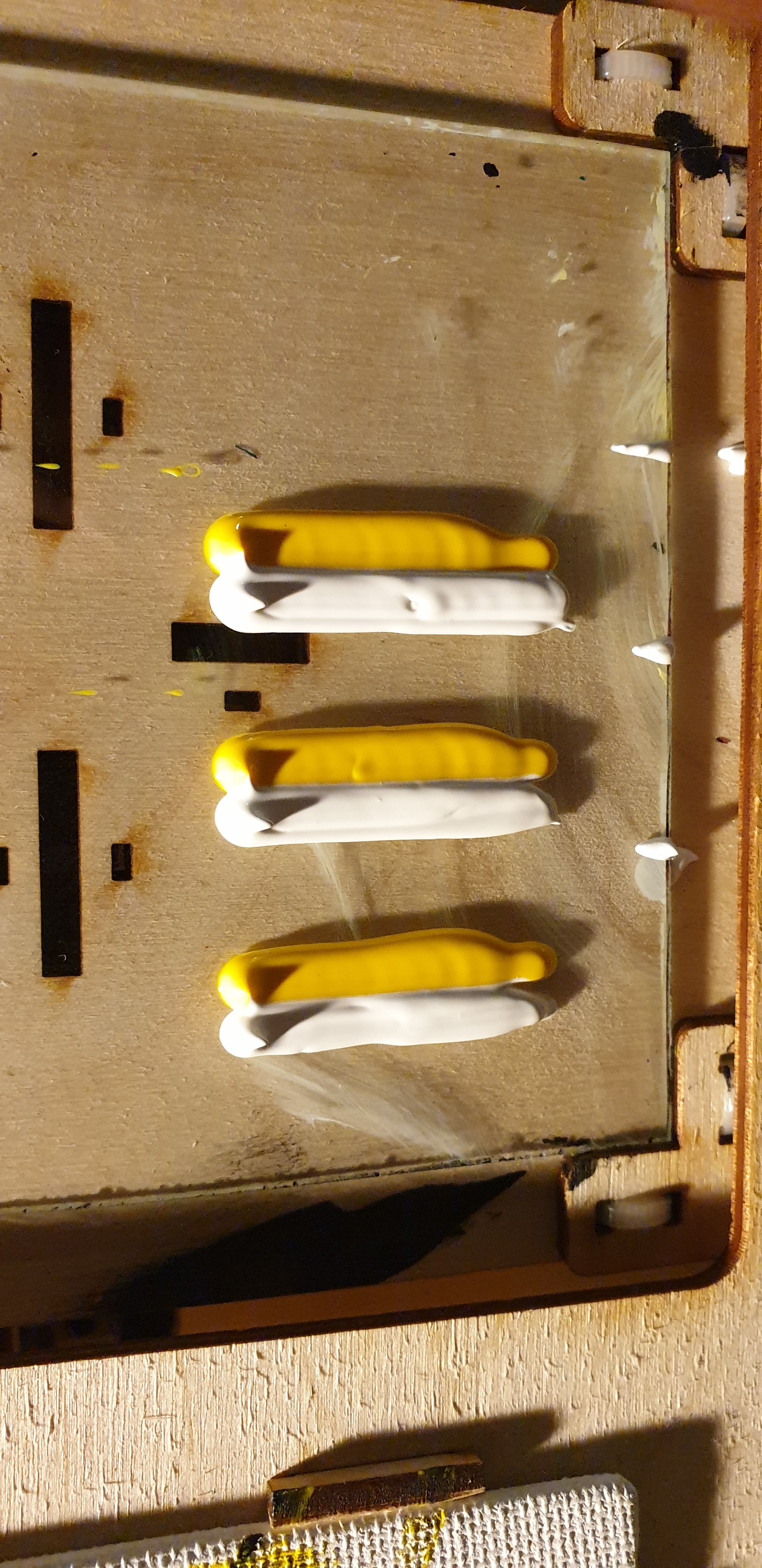
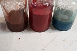
The If Then Paint cnc painting system adds value by automating the technical challenges that make custom paintings so expensive and time consuming. It can place paint on canvas with millimeters of precision, be programmed to perform any number of advanced brush stroke techniques, and mix hundreds of paint colors on demand. On top of that, it will perform all of these tasks through day and night without interruption. 

Operating the machine doesn't take years of practice and dedication either. Simply upload an image, define the painting parameters, load the raw materials, and watch the machine create your custom painting.

The Potential

  • A canvas painting productivity tool that artists can use to either create originals or replicate their best sellers faster than ever before.
  • A tool for crafters that reduces the amount of time and practiced skill it takes to add personalized painted embellishments to decorations and paper crafts. 
  • An flexible system architecture that gives makers and hackers the ability to develop their own digital image to paint stroke g-code algorithms and make mechanical enhancements to the machine with ease.
  • A platform that painters around the world can use to share techniques and recreate each others work.
  • A sign making tool for small businesses.
  • A canvas painting learning tool for young artists.
  • A platform for new canvas painting innovations.
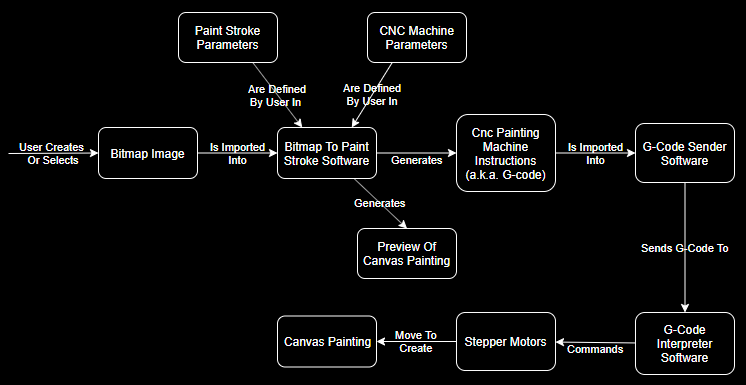
How It Works

History and Motivation

I began to develop a cnc machine specifically for canvas painting after competing in the 2017 RobotArt.org competition. There are two main reasons why I started - 1) during the competition, I recognized that several advanced software and mechanical innovations were required before cnc painting would be more accessible to a larger, less technical audience and 2) I was eager for a project that would stretch my software and mechanical design skills.

Development has continued on and off for the last two and a half years. I have considered transitioning to many other projects but I always come back to the cnc painter. It's challenges and potential are very exciting. 

R&D Phases

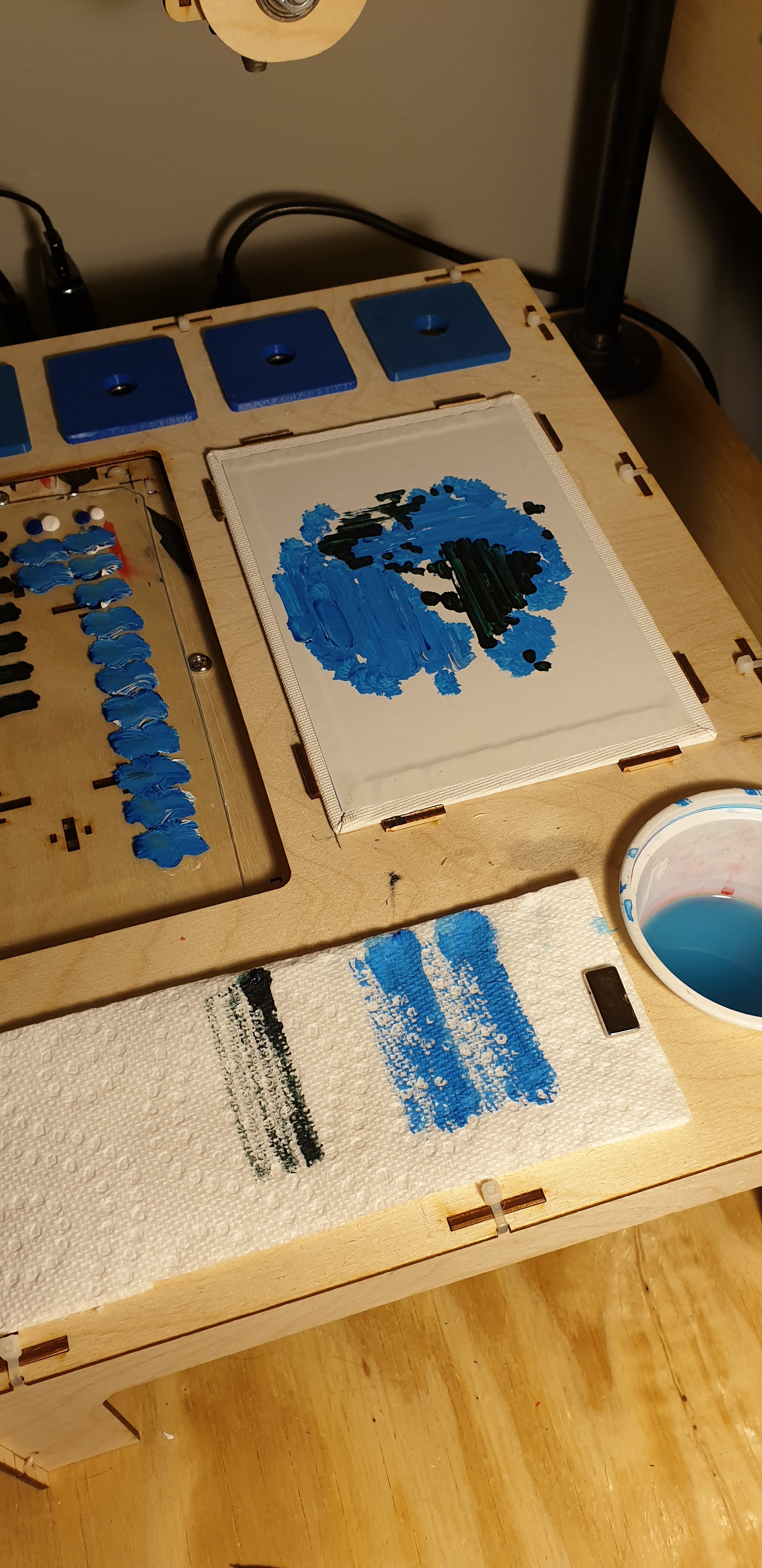
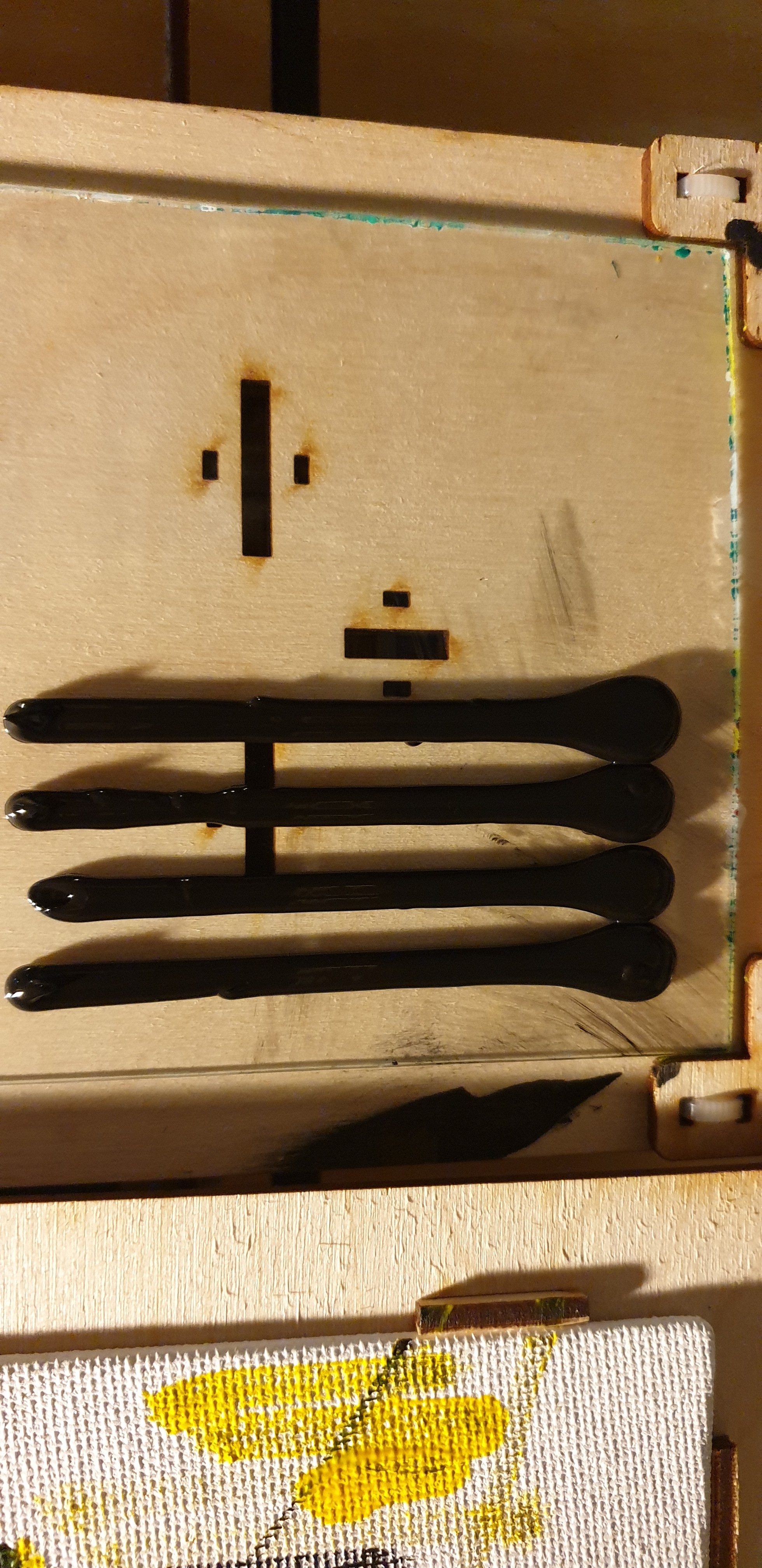
  1. Proof of concept. This initial R&D phase will prove out all the canvas painting technologies. The proof of concept phase will be considered complete when all technologies have been demonstrated in a single cnc painting operation.
  2. Market driven redesign. Not all of the proof of concept technologies will be viable for a marketable product. During this R&D phase, the system design will be refined to better align with market requirements.
  3. Design for manufacturing. At this point all of the R&D work specific to canvas painting has been completed and the system has been redesigned to better fit market needs. This phase involves further refinements to make the system easier and ultimately cheaper to manufacture.

Proof of Concept Phase - Design Requirements

For simplicity and practicality the proof of concept prototype adheres to the following design requirements:

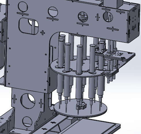
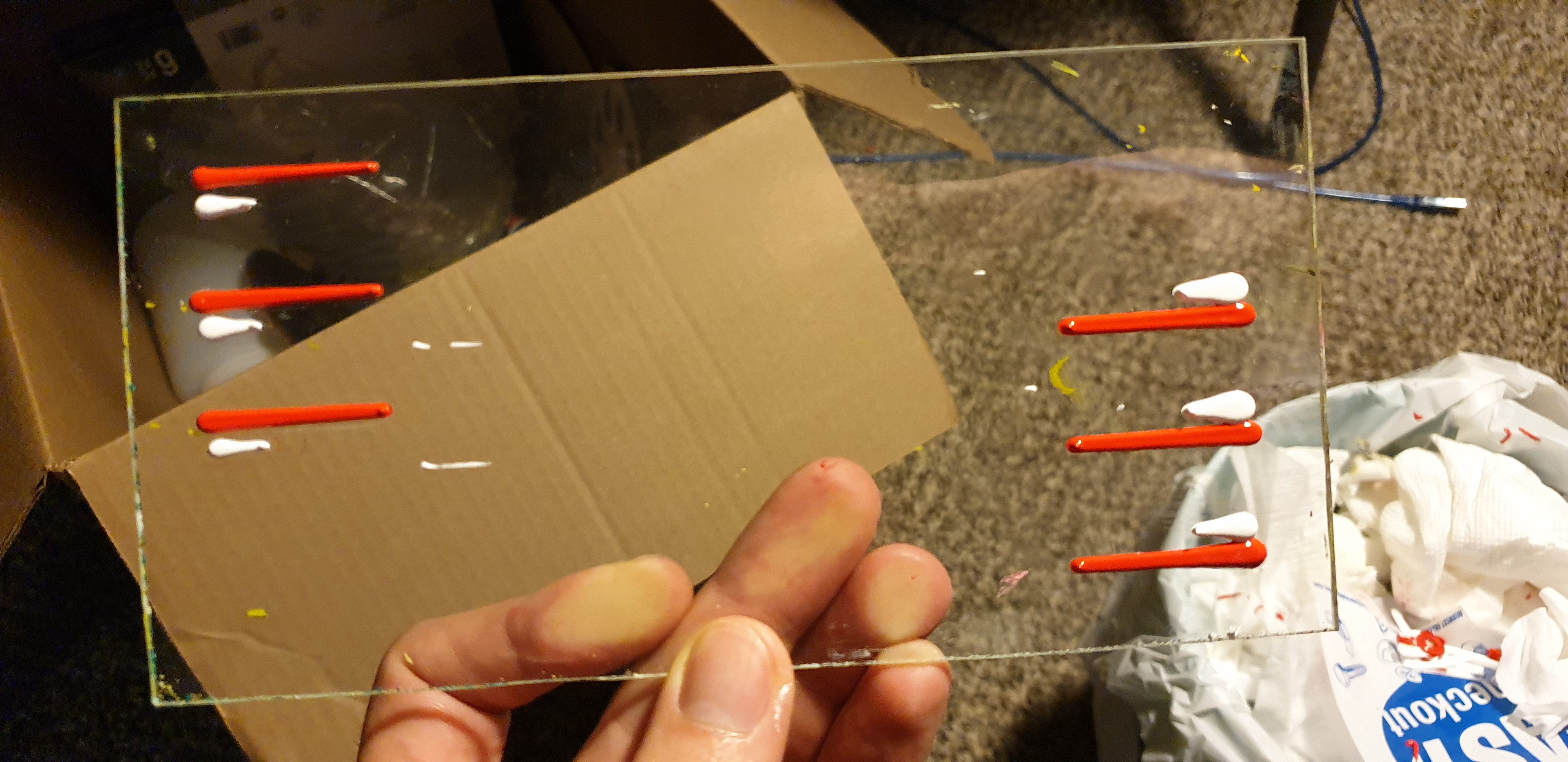
  • No feedback control. This decreases the complexity of the motion controller and software, but increases the complexity of the mechanical design. Without feedback, the mechanics used for painting have to be predictable and repeatable.
  • Common off the shelf and rapid prototyping components only. I live in an apartment so don't have immediate access to tools for fabricating parts. I also have a full time job. If the part can't arrive in the mail or be built in less than an hour, I don't have the time for it.
  • Unsupervised operation. Would anyone use 3D printers if you had to check them every five minutes? Of course not. It needs to complete a painting without taking up any user bandwidth.
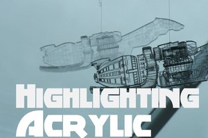
  • Acrylic paint. It dries quickly, can be bought at any hobbyist store, and is widely used by both professionals and hobbyist canvas painters....
Read more »

IfThenPaint_cnc_painter.STEP

3D model of the If Then Paint cnc machine

step - 21.67 MB - 08/02/2019 at 02:54

Download

  • paint mix ratio

    John Opsahl03/16/2020 at 04:18 0 comments

    I performed a manual run of the paint color mixing strategy this weekend to better understand the challenges. The paint color mixing strategy involves mixing together paints in known ratios, allowing the paint to dry, then capturing an average RGB value of the final color. With enough RGB values and associated paint mix ratios, I am hoping it will be possible to algorithmically match an digital image RGB color with a captured RGB paint color.

    The first thing I did was modify the paint g-code generation script so the paint management system would dispense a decreasing volume of green paint and increasing volume of white paint (from left to right) in 10% increments. The results are in the image below. The first dispense (far left) is not used; it is done to ensure that paint is flowing out of the syringe nozzles. Total volume of paint in each column is 0.05 cm^3. 

    After automatically dispensing the paints, I manually mixed them together and painted them on a white piece of paper. Then allowed the paint to dry. 

    I took a photo of the painted paper under repeatable light conditions (i.e. a photography light ring) with my digital camera. 

    I used a photo editing program to extract an average RGB value for each painted color. Paint mix ratios and RGB values are shown in the image below.

    Finally, I plotted the RGB values in 3D space. 

    Main takeaways from this exercise:

    • the digital camera measures smaller changes in color than I can perceive
    • paint colors can be far from their pure RGB representation (i.e. white paint under these light conditions is not (255,255,255))
    • linear paint mixtures in 10% increments may not result in human perceptible differences. I am guessing I could have achieved a perceptible color change at lower green to white ratios than 1:9. 
    • linear paint mixtures do not result in linear changes in RGB values
    • to be able to algorithmically match digitial image colors to paint colors effectively would require a much larger dataset

    My next step is to use this same process to mix green paint with red, blue, and yellow paints. I want to understand the size of color gamut I can achieve using mixtures of two paint colors.

  • Where to next

    John Opsahl03/07/2020 at 18:09 0 comments

    At this point, the cnc painter satisfies the proof-of-concept requirements I defined for it last fall. It is time to look back on what has been accomplished and layout where this project is going next.

    At face value the cnc painting system I have developed so far isn't that impressive. A machine that takes up 2ft x 4ft of my living room and requires software that took me over three years to develop can only create paintings that are at most 5in x 7in and look like a toddler made them. So maybe the paintings themselves are not yet interesting enough that someone would buy them, but that hasn't been the main focus of this project.

    The main goal of this project has been to solve and simplify many of the previously unsolved technical challenges of cnc painting. Under this direction, I feel like I have been able to contribute many new technologies to cnc painting as a whole. The most valuable new technologies being a fully automated paint management and dispensing system, a generalized algorithm for developing paint stroke paths from bitmap images, a low cost six axis cnc machine, a branch of grbl-Mega-5X for controlling up to six micro-step stepper motor drivers with grbl, a low cost tool change system, and a methodology for controlling brush operations during the cnc painting process.

    The fun part is that all that I have developed so far with this project is really just the tip of the ice berg. I would say I am only 30% complete with my vision of cnc painting technology. The next major challenges to tackle are a full implementation of the paint color mixing strategy (automated paint mixing) and refining brush control during paint dipping and canvas painting operations with B and C axis movements (origin and axis orientations). Once these challenges are complete, the mechanical capabilities of the current machine may be the biggest hurdle for future development. In which case, it will be time to redesign the six axis brush control system for increased speed and a larger work space.

  • "Hello, World!"

    John Opsahl03/04/2020 at 03:44 0 comments

    A video showcase of all the latest features:

    • dispensing small beads of paint
    • mixing paint using the brush
    • using multiple tools on a single painting
    • linear wipe rows on the towel
    • A axis movements specific to tool axial symmetry
    • A axis movements prior to brush dipping and wiping on the towel

    Stats:

    • two paint brushes - 1st is a round brush, 2nd is a flat brush
    • four stock paint colors mixed to create two custom paint colors
    • 25 minutes sped up to fit within 4 minutes 42 seconds
    • 2700 lines of g-code

  • first painting with automated paint mixing

    John Opsahl03/01/2020 at 05:57 0 comments

    The previous strategy to dispense paint in bead lines was abandoned. It was too difficult to find the correct dispense rate and dispense the correct paint volume per unit length on the palette. The main challenge with determining the correct dispense rate is the dispense response of the syringe. There is a delay between when the syringe plunger is advanced and when paint actually comes out of the syringe. The causes of the delay that I haven't been able to control and quantify are air pockets in the syringe and the viscosity of the paint. I check for large air pockets in the syringes by pressing down briefly on the syringe plunger. If it the plunger bounces back to the original location, you know there is a air pocket in the syringe. Even with this method I am still not able to detect all the air pockets. And the viscosity, it seems to vary by the batch of paint and the age of the paint. I found that the challenges of air pockets and paint viscosity can be avoided by dispensing paint in small beads and using a delay between each dispense that is long enough for the volume of paint to leave the syringe. This method results in the correct volume of paint being dispensed on the palette and an easier paint dispense calculation, but ultimately, is much slower than the previous paint bead line dispense method. 

    Below is a gcode tool path visualization of the small paint bead method and an image of the paint palette after the machine has performed these gcode operations. Notice that one of the white paint beads is missing from the palette; this was due to an air pocket in the syringe that I wasn't able to remove.

    The significant changes on the paint brush operations since my last post have been with the parameters that define each brush, the paint mixing operation, and the towel wiping operation. Brush movements are now controlled with parameters that reference what percent of the tip of the brush will be in contact with the work space component (i.e. palette, canvas, towel, or water). For example, the z_palette_load_percent of 0.4 (defined in the tool_profile objects) would result in 40% of the paint brush tip being pushed into the palette during a paint dip (i.e. brush loading) operation. The paint mixing operation is fairly simple, but took several tries to get right. It involves staring on one side of a paint bead group, wiping toward the center of the paint bead group, lifting up, moving to the other side, wiping in the other direction toward the center, and repeating this movement multiple times. The towel wiping operation now orients the A axis 90 deg prior to wiping on the towel and follows a linear pattern instead the previous circular pattern. 

    Below is a gcode tool path visualization of the brush operations and an image of the painting that results. I have defaulted to using a simple "Hello World" painting for testing all the operations.  

    At this point, the machine can mix up different paint colors and paint on canvas without supervision but I still have more to explore with which paints to mix together and in what proportion to achieve the desired paint color and finer brush control to achieve higher levels of detail in the painting. I am glad to have made it this far and look forward to the next set challenges on this project. 

  • first successful paint, code changes, 10ml syringes, paint color mixing

    John Opsahl10/29/2019 at 16:38 0 comments

    A lot of progress towards completing the proof-of-concept prototype machine has been made over the last month and a half. First off, the code restructure I completed in August really paid off. After only about a week of tweaking, the paint management system successfully dispensed paint on the palette and then the six axis cnc brush control system used that paint to create a crude image of my cat Jackie. It was so fun to watch it complete the first end-to-end painting operation. I will get around to posting of video when I get the paint color mixing operation working as well.

    Much of the project work has been in the code. I added a longest allowable stroke length parameter to the line scan algorithm. With the addition of this parameter, the user can now control both the shortest and longest brush stroke lengths that will be used to construct the painting. It should be possible to create a pointillism effect if the the shortest and longest stroke length parameters are set equal to each other, but I haven't had a chance to test yet. An image of the algorithm at work with the new longest stroke length parameter is shown below; notice that lines are no longer than a certain length. Other changes to the code include the current effort to restructure the code for paint color mixing. This involves adding capabilities to the dispensing operation and image color to paint color match so a single paint color is treated as a composition of multiple "stock" paint colors. "Stock" paints being the the paints currently loaded in the syringes of the paint management system.

    The only recent mechanical changes to the system has been switching from 30ml to 10ml syringes and increasing the stiffness of the syringe push plate by adding a second plate. After talking with my step-dad about paint mixing, I realized that I needed no where near 30ml of each paint color to paint a 5in x 7in canvas. I ordered some blunt tip 10ml syringes online and to my surprise the tips did not clog as easily and it's much easier to dispense smaller beads of paint. I have since updated the syringe carousel on the paint management system to accommodate 10ml syringes. I noticed some deflection in the syringe push plate when only one plate was used. It's hard to say for sure, but It seemed like the deflection was influencing the amount of paint that gets dispensed at the beginning and end of each paint bead. I added a second plate and haven't seen the deflection since. See changes modeled in image below.

    At the start of this project, I didn't put much thought into how I would use the system to physically dispense and  mix two (or more) stock paint colors together to create new paint colors. Its taken several nights after work to arrive at a solution that I am 85% confident will work. The first challenge is just dispensing paints in different proportions. It's easy enough to create paint colors that consist of 50/50 of two stock paint colors because all you have to do is refine the machine's ability to create consistently sized paint beads. Then just dispense two of the paint beads next to each other and mix the colors together with the brush. If I was on some kind of deadline for this project, I probably would have taken the 50/50 route, but in the long term the 50/50 method puts a hard limit on how many paint colors you can create from the stock paints available to you. To achieve the ability to dispense paints in almost any proportion, I am developing a method to dispense different sized paint beads. With this method it should be possible to achieve all possible colors (within limits of smallest paint bead that can be dispensed) that can be created by mixing the stock paints. Proportions such as 20/80, 5/95, 11.75/88.25, etc. should be possible.

    I have done a lot of experimentation with dispensing paints on the palette. Here are some of the results/failures.

  • limit switches and homing sequence

    John Opsahl09/07/2019 at 17:10 0 comments

    I was having some issues last weekend removing noise on the paint management system axis limit switches. The consequence of noise being that even when none of the limit switches were pressed, grbl would stop the machine an indicate a hard limit switch alarm. This seems to be a fairly common issue among grbl users when wiring the limit switch signal wires directly to the Arduino. The grbl wiki recommends using an RC circuit or better yet opto isolation - https://github.com/gnea/grbl/wiki/Wiring-Limit-Switches. I tried the RC circuit method with the recommended resistance and capacitance values but still got false hard limit switch alarm trips. After a few hours of troubleshooting, I discovered that by routing the limit switch signal wires away from the stepper motors and stepper motor power wiring the false alarm trips would no longer occur. The paint management system has operated well since rerouting the signal wires, but I am skeptical whether the machine will be able to operate without false alarm trips for durations up to several hours without a robust signal filter or isolation solution. Though at the moment, I am grateful to have found a simple solution.

    After resolving the noise issue on the limit switch signal wires, I was able to set the homing sequence and perform the homing operation on both machines. Previously I had issues with getting the grbl homing operation to work. Using the "show verbose output" feature of the Universal Gcode Sender open source application (https://winder.github.io/ugs_website/), I discovered that the unused axis limit switch pins where being treated as "activated". Connecting all the unused limit switch pins to ground solved the issue and the homing operation now works great. 

    The six axis brush control cnc machine homes to X-, Y-, and Z+. The homing sequence is Z+ then X- and Y-.

    The paint management system homes to X-, Y+, Z-, and B-. The homing sequence is X- and Y+, Z-, then B-.

    During the process of developing the homing sequence, I realized that some of the dimensional control parameter datums needed adjustment. For example, on the paint management system I originally planned on homing to Y- but at that end of the machine there isn't any room to home the Z axis (the water dish is in the way). So after established the appropriate homing sequence for each machine, I spent some time updating the dimensional control parameter values that tell the machine where in the workspace objects (i.e. water dish, paint palette, canvas, etc.) are located. All of the new values are captured in the If Then Paint Image2Gcode code on GitHub (https://github.com/johnopsahl/IfThenPaint_Image2Gcode).

  • open source code

    John Opsahl08/27/2019 at 04:23 0 comments

    All code for the If Then Paint project has been released under LGPL-3.0 on GitHub. 

    Link to the repository: https://github.com/johnopsahl/IfThenPaint_Image2Gcode

    I will continue to update the code and documentation in the GitHub repository as this project develops.

  • bitmap image to paint stroke g-code - part 4

    John Opsahl08/23/2019 at 19:35 0 comments

    At this point in image to g-code process we know what lines to paint and what tool and paint color to paint them with. What we haven't accounted for are all the dynamics that come into play during the cnc painting process. How far can the brush paint on canvas before it needs to go back for more paint, how often does the brush need to cleaned so paint doesn't dry and build up on the bristles, what movement is required to load the brush with paint, how much paint is required to create the painting, is there enough room on the palette to fit all the paint needed to create the painting, etc. Solving these challenges requires more of a bookkeeping mindset than a mathematical one.

    The first step of addressing these dynamics is to understand how much paint is required for each layer of the painting. Only three values are needed to arrive at the layer paint quantity estimate - the total distance the paint brush travels on the canvas during the layer, the maximum distance the paint brush can travel on the canvas before it needs to be loaded with more paint, and the quantity of paint required to load the brush. The latter two are determined through experimentation.  

    The next step after determining how much paint is required is to map out where on palette to dispense the paint both so the paint management system knows where to dispense the paint and the six axis brush cnc machine knows where on the palette to go to load the brush with more paint. I have chosen the approach of dispensing beads of paint in rows that run the long dimension of the palette. If the length of bead that needs to be dispensed is longer than the length of the palette, the remaining bead length will be dispensed on the next bead row.

    After the palette paint map is finished, writing the machine instruction g-code is just a matter of following the correct sequence of operations: 1) get the tool from its dock, 2) wet the brush, 3) load the brush with paint color 1, 4) paint on the canvas, 5) load the brush with paint paint color 1, ... 20) clean the brush, 21) load the brush with paint color 2, ... Each operation having unique movements and control parameters. Some that can be calculated and others that have to be determined experimentally. This is where the dimensional control parameters that I have described in a previous project log come into play.

    Since many of the control parameters are experimental, the g-code writing script I developed writes all the relevant object control parameters at the appropriate location in the g-code file. I suppose as this project becomes more mature, these parameters may become standardized through experimentation and no longer need to be logged in the g-code file. Like I said; it's mostly bookkeeping. 

    This concludes the bitmap image to paint stroke g-code project log series. I am always happy to answer questions or provide a higher level of detail upon request. Please post any questions and comments to the main project page. 

  • bitmap image to paint stroke g-code - part 3

    John Opsahl08/23/2019 at 16:53 0 comments

    Defining layers is the next step after generating stroke lines from the image. Layers are a high level structure that associate the stroke lines with an available paint color and tool profile. Layers in this context can be thought about in the same way that you would think about layers in an image manipulation program like Adobe Photoshop or GIMP. The layers beneath will be painted first and the layers on top can overlap the layers beneath. 

    I usually follow one of two thought processes when assigning a paint color to a layer: 1) I let the software automatically select the paint color that is stocked on the machine and is closest to the rgb value of the image color of the stroke lines, 2) If I want to abstract the colors of the painting, I manually select any color that is stocked on the machine.

    The tool profile defines what tool is to be used and in what way. I can think of at least ten ways to orient a flat brush on a canvas to create different brush stroke effects. A tool profile defines just one of those ways.

    After layers have been defined, we can create a preview image of the painting. The painting preview image below is a continuation of the example from part 1 of this project log series. It is black instead of dark green because I had the software automatically assign the stocked paint color that was the closest match to the image color. Apparently, the dark green was closer to black than the green that is also stocked. 

    If after viewing the painting preview you don't like what you see, it's easy enough to regenerate stroke lines using different input parameters, assign a different paint color or tool profile, and create another painting preview image. 

    Creating the painting preview image concludes the image processing component of the image to g-code process. The steps that follow are specific to developing the If Then Paint machine g-code machine movement instructions from the layer structures.  

  • bitmap image to paint stroke g-code - part 2

    John Opsahl08/23/2019 at 13:31 0 comments

    This project log is going to focus on the line scan algorithm parameters used to generate paint strokes from a bitmap image. I described the longest line selection component of the algorithm in a previous project log (https://hackaday.io/project/166524-if-then-paint/log/165761-generate-paint-strokes-from-a-bitmap-image) so I will not touch on it here. 

    I like to think that the If Then Paint line scan algorithm is just the beginning of what is possible. There are other unique approaches to generating paint stroke lines from bitmap images that have not been explored yet. Each possible of creating unique painterly effects. Wouldn't it be great if we had a cnc painting machine platform to test out new algorithms and have multiple algorithms available in a single software package? -> Well, welcome to the If Then Paint project.

    At a high level, the If Then Paint line scan algorithm works by scanning the paint brush profile size across the image at different angles, looking at whether each paint brush profile location has a high enough percentage of pixels of the scan color to be considered a valid location, then connecting adjacent valid brush profile locations into valid stroke lines. It is a computationally heavy, brute force method that has worked well so far to generate paint strokes from any bitmap image. 

    The following line scan algorithm input parameters can be adjusted to create different painterly effects:

    • Scan Angle. The scan angle is the angle (relative to the horizontal) at which the algorithm scans the brush profile size across the image. Specifying the number of scan angles to use is a balance between ensuring that the stroke lines are scanned at enough angles to follow the contours of the image and the duration it takes to perform the line scan. The number of scan angles is the most influential factor on how long it takes to perform the line scan algorithm. A low scan angle count will give the painting a more grid or cross hatch look. A high scan angle count will make the paint strokes look more organic and flowy.
    • Profile Width. The profile width is the width of the stroke profile that gets scanned across the image. A larger profile width is representative of a larger physical brush width and vise versa. Larger brush profiles are good for covering large single color areas. Smaller profile widths will capture finer image details.
    • Profile Length. The profile length is the forward increment that the stroke profile advances along the scan angle. A smaller profile length will result in better coverage at the image color boundaries but will also increase the run time of the algorithm. 
    • Color Match Threshold. The color match threshold is a percentage value used to validate or invalidate a profile location. If the percentage of pixels within the profile location that match the scan color is greater than or equal to the color match threshold, the profile location is considered valid. A smaller color match threshold will make the stroke lines of a line scan more dominant at the color boundaries. Too high of a color match threshold can make a no man's land between color boundaries; where no stroke profile has a high enough percentage of pixel color matches to be valid. 
    • Scan Line Overlap. The scan line offset overlap is the overlap between two adjacent and parallel stroke profile scan lines as a percentage of profile width. It translates directly to physical paint stroke overlap. A scan line overlap of zero will result in no overlap between parallel strokes. A larger scan line overlap decreases the distance between scan lines which increase the number of scan lines required to cover the image and increases the algorithm run time.
    • Minimum Line Length. The minimum line length parameter controls the minimum allowable stroke line length. I use a small minimum line length that is just larger than zero when I want to reduce the number of "dot" strokes....
    Read more »

View all 25 project logs

Enjoy this project?

Share

Discussions

Elliot Williams wrote 03/04/2020 at 19:10 point

Was just talking about your bot last week on the podcast.  The color mixing is really the coolest feature -- and that swirl-the-brush bit!  Glad to see it's still making progress. 

It's a work of meta-art!

  Are you sure? yes | no

Tom Nardi wrote 08/03/2019 at 04:58 point

Love the use of keyless drill chucks to hold the brushes, brilliant reuse of a common part.

  Are you sure? yes | no

Similar Projects

Does this project spark your interest?

Become a member to follow this project and never miss any updates