 Jeremy Ruhland
Backdated Oct 19th, 2016:
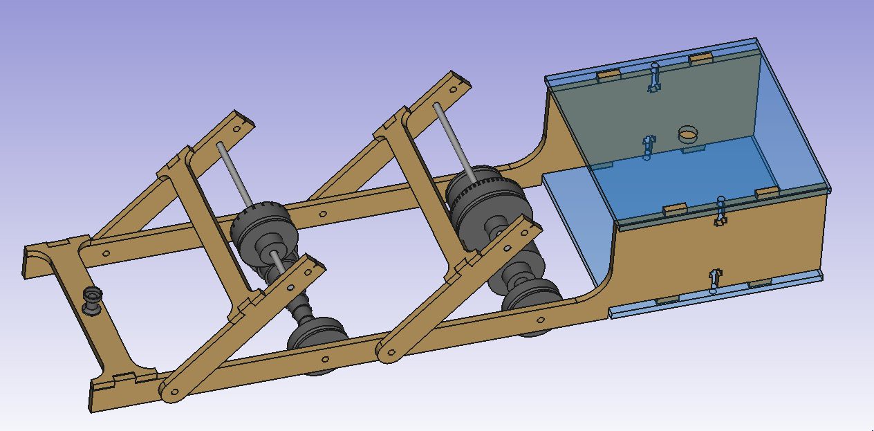
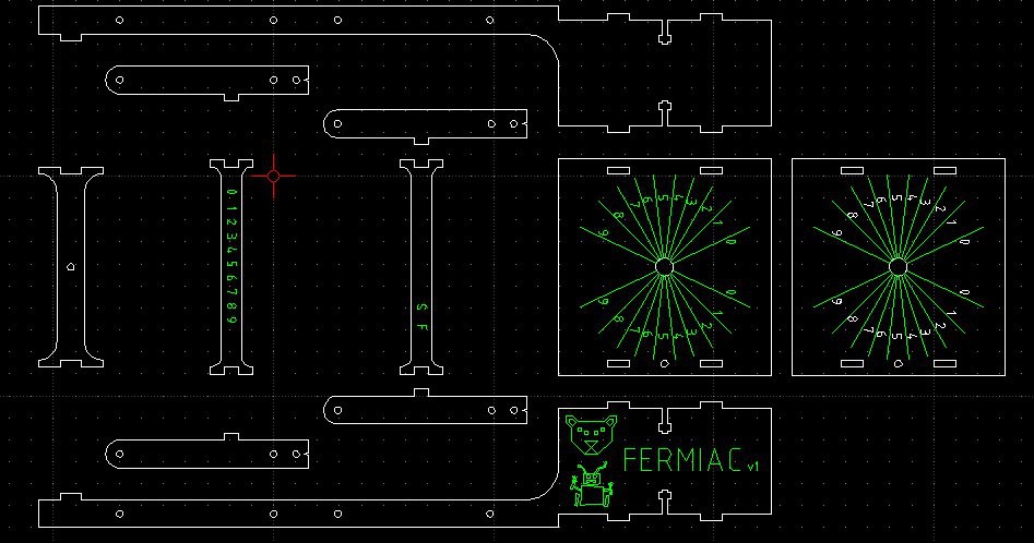
The 2D design has been completed, ready for fabrication.
You can see a small collision between wheel C and its arm support
strut, this is because I duplicated wheel E's arms and translated them
over to support wheel C. The actual wheel C arm support strut has its
tab slightly lower down.
The two square parts are going to be cut from acrylic and the remainder from 3/16" plywood. Green is my etching layer. For some reason the text on the far right turned white during the last copy/paste but its since been corrected. The angles of the etched lines in the acrylic were precomputed by Enrico Fermi to be equal to the angles that neutrons scatter off atoms and the directions that daughter neutrons may take after fission events.
I'm using the old makerbot inspired tab/slot/t-nut right angle joint to hold the acrylic to the side supports. This design should be more mechanically sound than the original FERMIAC design which used four screws in close proximity to hold the acrylic to brass support bars and another set to hold the acrylic plates apart between brass standoff bars. The arms and struts on my design will be screwed and glued as necessary.
The original FERMIAC kept its axles in place with washers retained by linchpins that passed through a hole in the end of each axle. On my version I'm simply sizing the length of each axle to sit flush with the surface of the side supports and arms and placing a piece of tape over the holes such that they axle won't slip out.
As a funny note: apparently the S/F neutron speed indicators on Fermi's original FERMIAC were accidentally ordered backwards and corrected later with a piece of tape. I found out about this too late and made the same mistake on mine. Coccetti corrected this on his 2015 replica.
Discussions
Become a Hackaday.io Member
Create an account to leave a comment. Already have an account? Log In.