0%
0%
ESP32 video deck
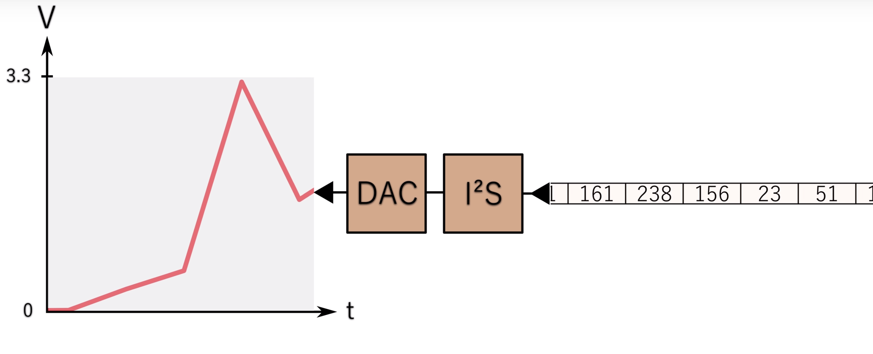
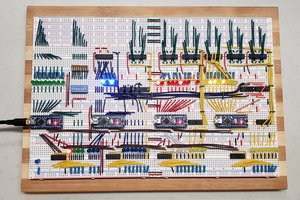
This board switches between two video inputs and an internal composite video generator. Complete with a LM1881 hardware sync separator
 [ E C C 0 ]
Become a Hackaday.io member
Already have an account? Log in.
Just one more thing
To make the experience fit your profile, pick a username and tell us what interests you.
Pick an awesome username
hackaday.io/
Your profile's URL: hackaday.io/username. Max 25 alphanumeric characters.
Pick a few interests
Projects that share your interests
People that share your interests


 Patrick LeBoutillier
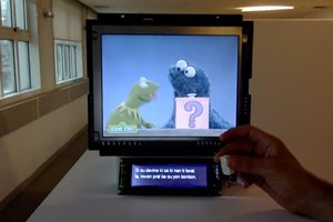
 jasoneppink
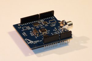
 MagicWolfi
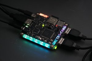
 Santiago Germino
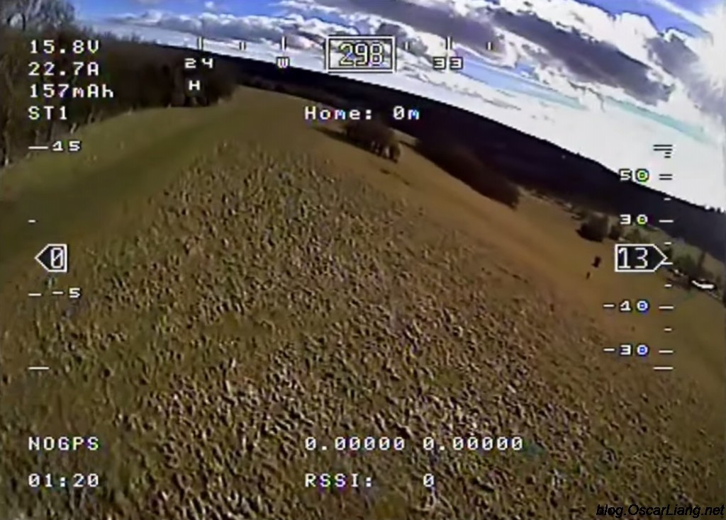
That's a neat idea!!! I would love to see this through, we need more "game modes" in FPV racing!!
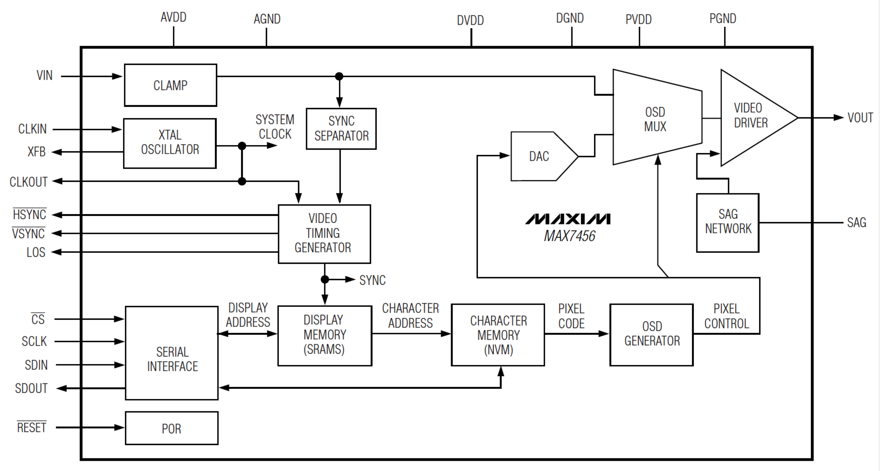
I have no idea how to fix this, but it might be the supporting circuitry of the MAX7456, since on your video, only one of the OSD's goes out, and the standard flight controller one is still the MAX7456 / AT7456, which does not??
It might also be the fact that you are chaining two OSD's (if that's what happens) but i don't think it should matter that much.
It would be great if you documented your project here or on github so we can take a closer look ;)