 Carbon
As mentioned above, the SineStick is intended to be the complementary opposite of the RTL-SDR; half of a full radio.
Sort of. A true opposite of the ADC in an SDR would be a DAC - a digital analog converter.
Instead this device utilizes a programmable oscillator and attaches it to a computer via USB. This significantly reduces what kind of protocols can be sent with the advantages of simplicity (both in circuit and software), and low processing overhead.
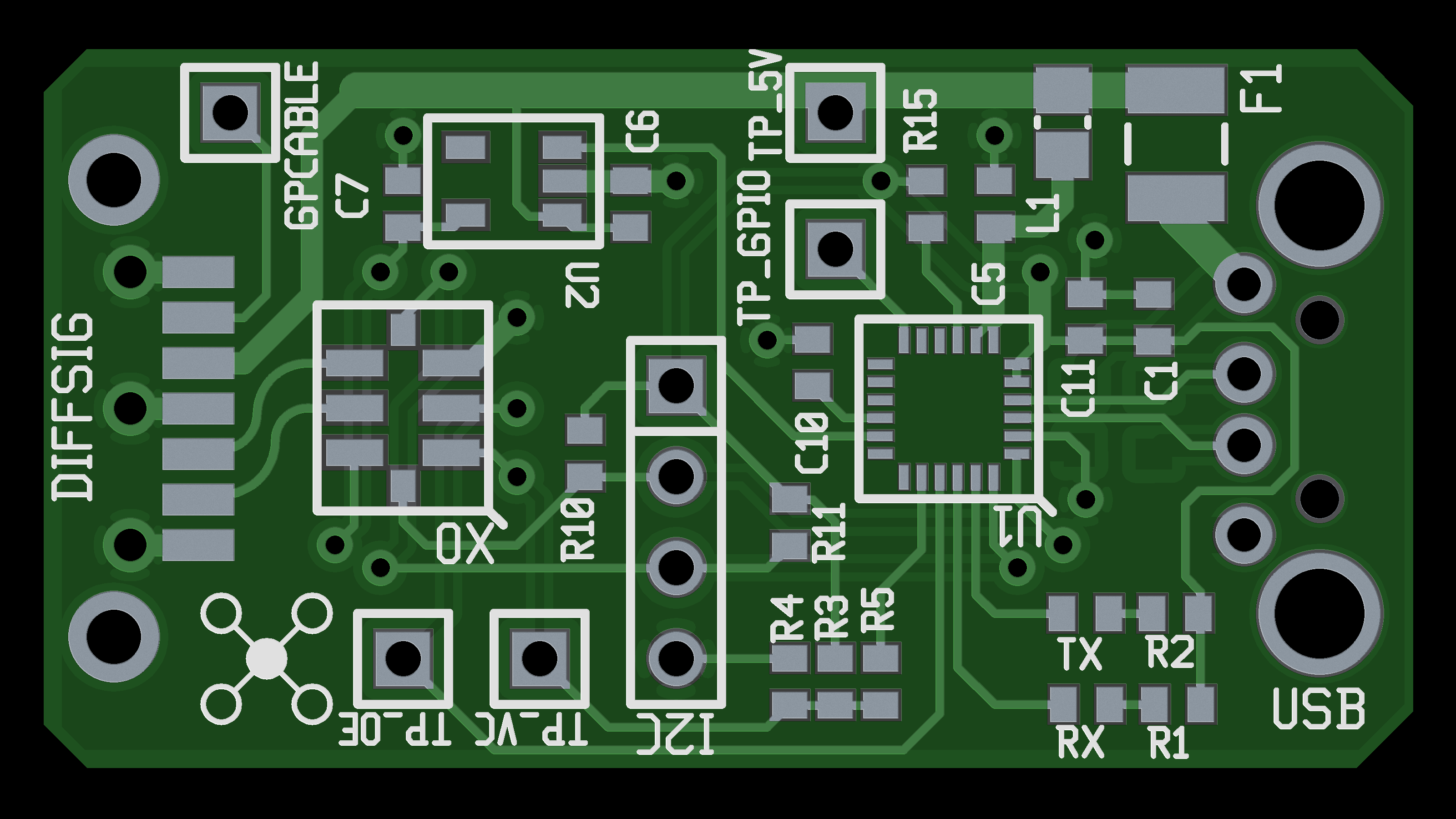
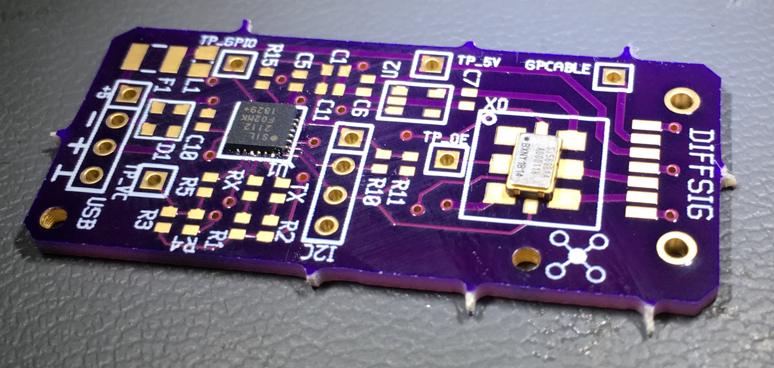
The heart of SineStick is the SiLabs SI569 - a VCXO (voltage controlled oscillator) with an I2C interface. This device can be programmed to output any frequency between 0.2 and 3000 MHz.
As always, there are caveats - with large freq changes the output take times to stabilize, and the I2C bus isn't known for it's blazing update rate. If somebody manages to set up a GSM network with this, I will be very impressed.
On the flip side, this part also has a voltage input that allows output frequency control up to +/- 190 ppm. That works out to a controllable variation of about +/- 174 kHz when at 915 MHz center. Perfectly fine for some simple FSK.
Of course, this oscillator is useless if we can't control it. I initially considered a microcontroller - I was attracted to the idea of users being able to develop their own baseband software - but after some thought I realized this was antithetical to the idea of the RTL-SDR and repurposed VGA adapter. These units just deal in raw data, they aren't radios unto themselves.
I also realized that having to flash firmware onto every device (and then test them) would cost a significant amount of time and money if I ever ended up producing these units. I just needed a bridge chip - something I could drop in to connect I2C to USB.
Eventually I settled on the SiLabs CP2112 USB-to-I2C bridge chip. It won out as it has the very interesting feature of simply enumerating (on Linux at least) as an I2C bus. That's right - load up i2c-detect from lm-sensors and the CP2112 shows up as an SMBus adapter.
I had all my major parts - now to stick them together.
Further design decision comments and a blow-by-blow development blog continue down below.
Be sure to check out the gallery for the schematics and photos, and the OSHPark link on the left to order your own boards.
I'm excited to see what people can do with this!
 Colin O'Flynn
 Chris Stratton
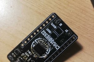
 Gee Bartlett
 Stephen Holdaway
This is super cool. The Si569 has quite a high price point still. Are there more affordable alternative chips (at the cost of reduced frequency coverage)?