 Kyle Isom
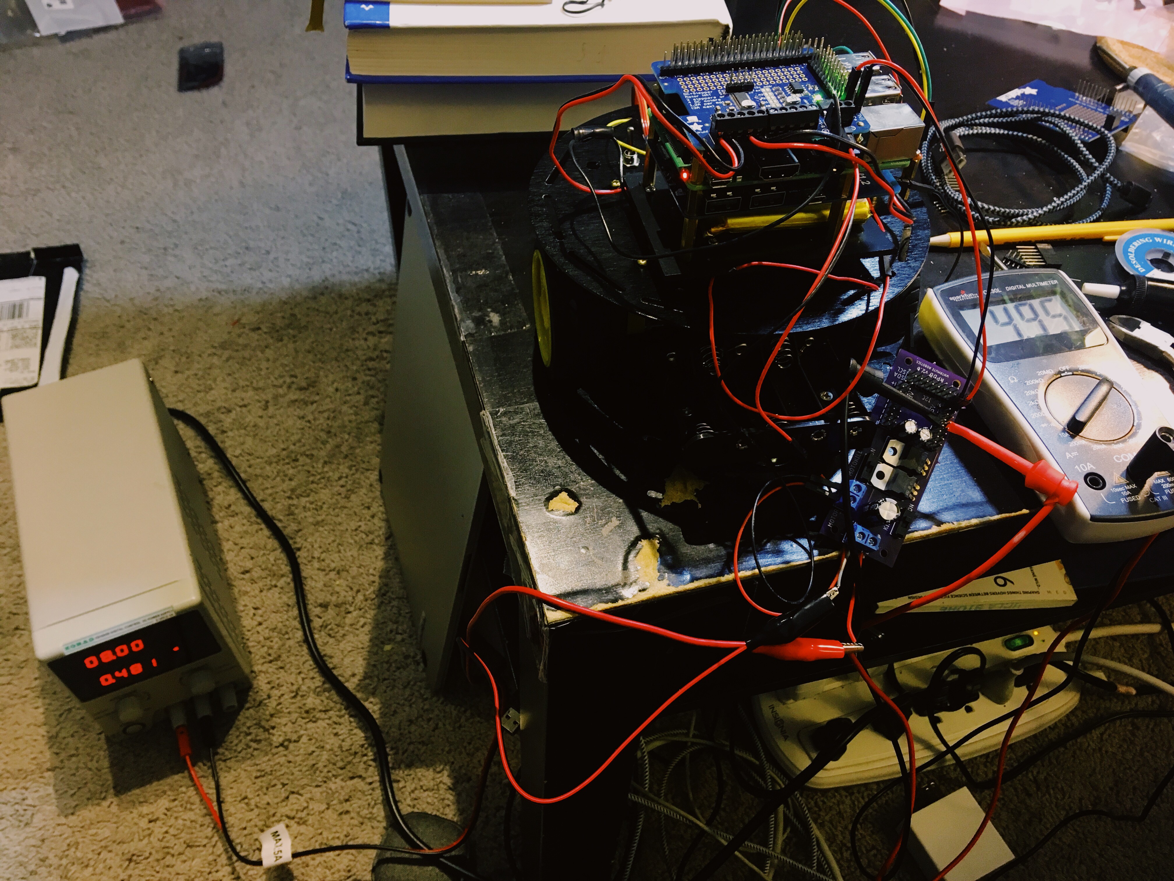
The basic problem is this: my controllers and peripherals are 3.3V or 5V, but the motors need as much voltage as I can throw at them.
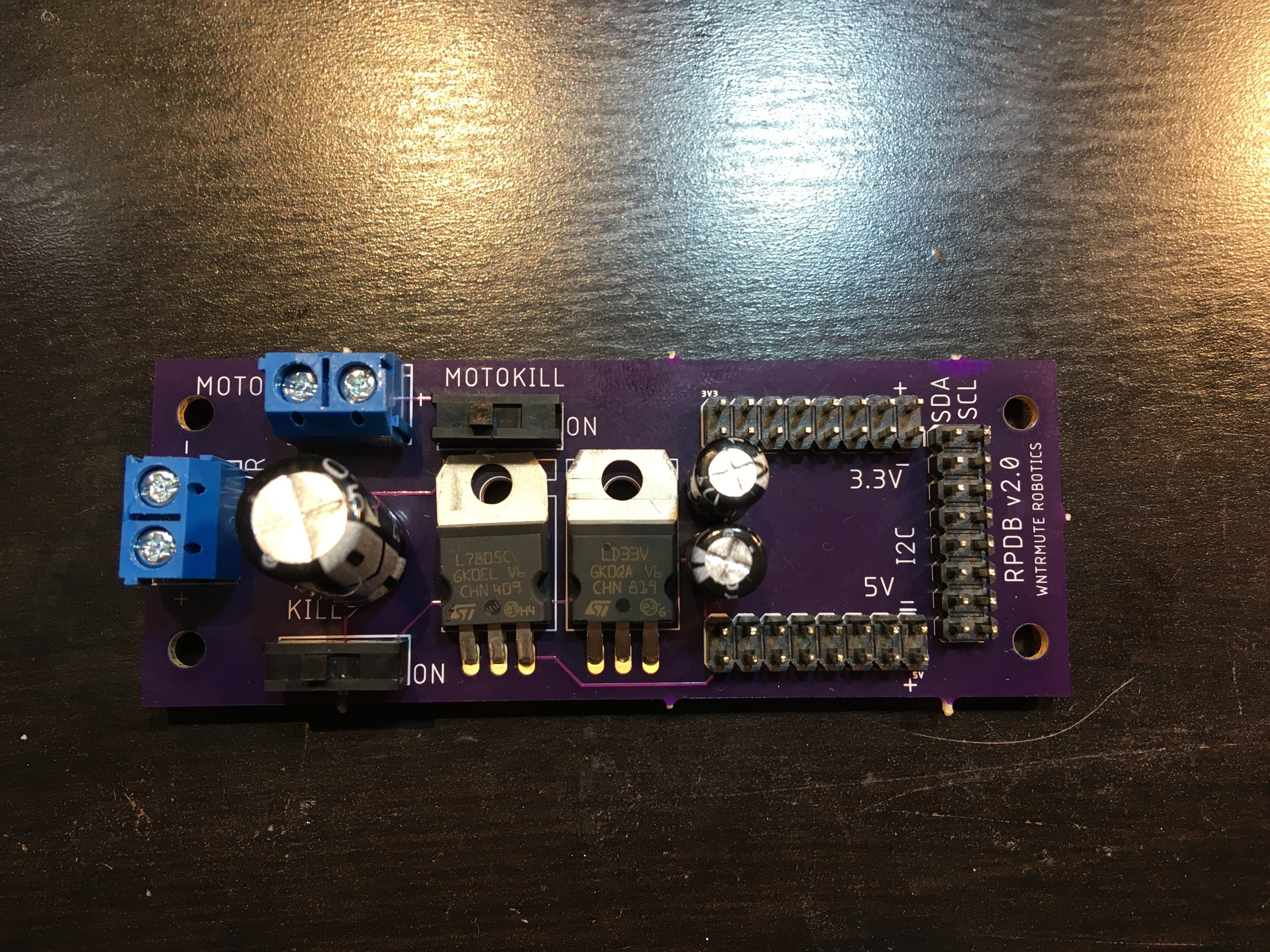
The board is split into several sections.
The first part is the power intake. It's a screw terminal input for the most flexibility, and adds in a kill switch and large decoupling capacitor. This splits out to a direct power output to the motor controller with a motor kill switch to let me test the other parts of the robot without worrying about the motors. I put the cap before the switches so that the capacitor discharge doesn't affect the time to kill the system.
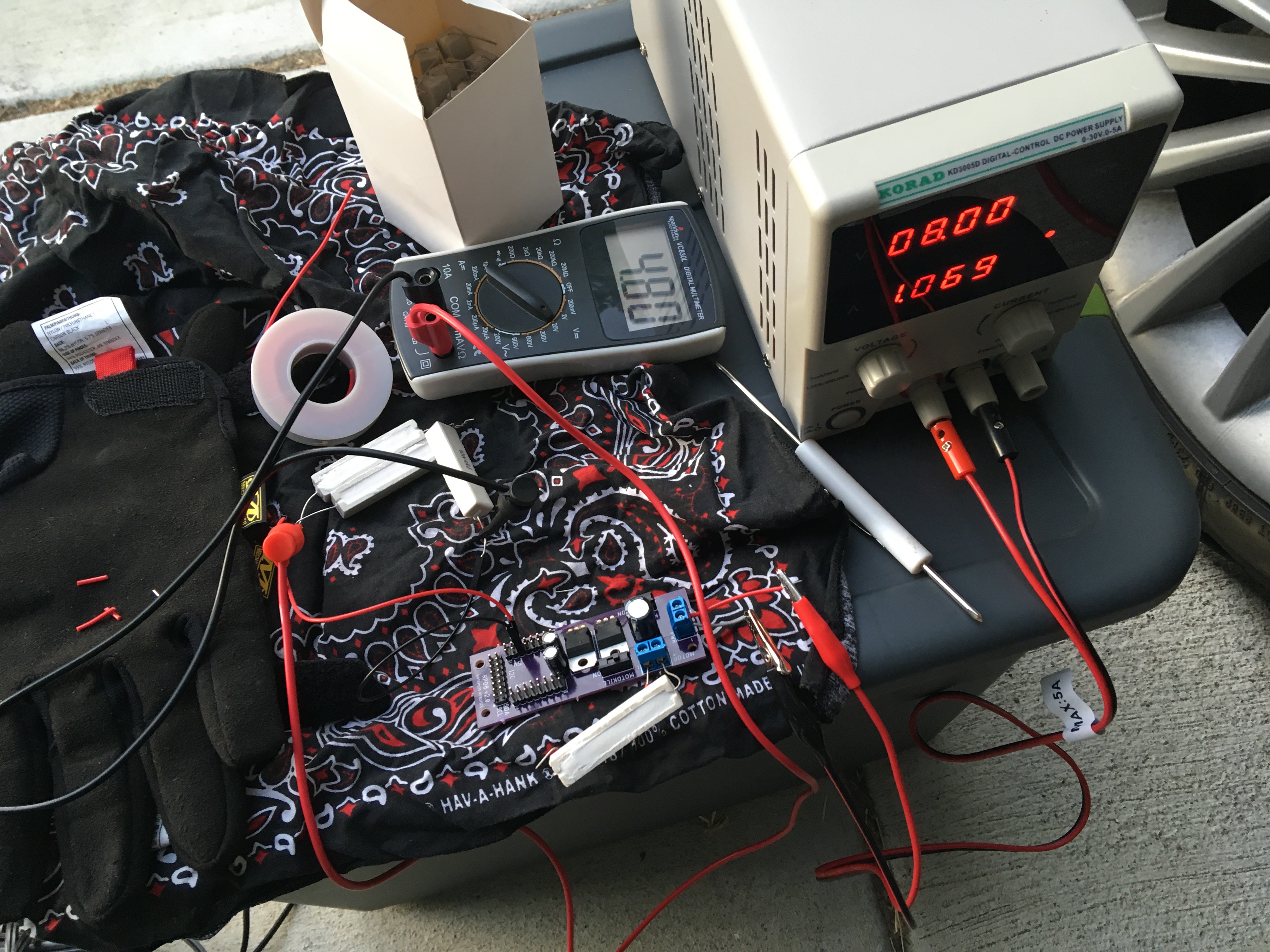
There's a pair of voltage regulators: an LD1117 to provide 3.3V and an LM317 to provide 5V. These have decoupling caps placed after them. They go to a set of headers that provide power connections for the relevant systems.
Finally, there's an isolated I2C expansion that lets me add up to seven I2C peripherals via standard header.
Revision history:
2.0: fixed capacitors (the caps were in-line with the circuit instead of acting as decoupled caps).
1.0: First pass.

 MagicWolfi
 emuboy
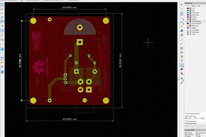
 Mark Rehorst
 Daniel Katz
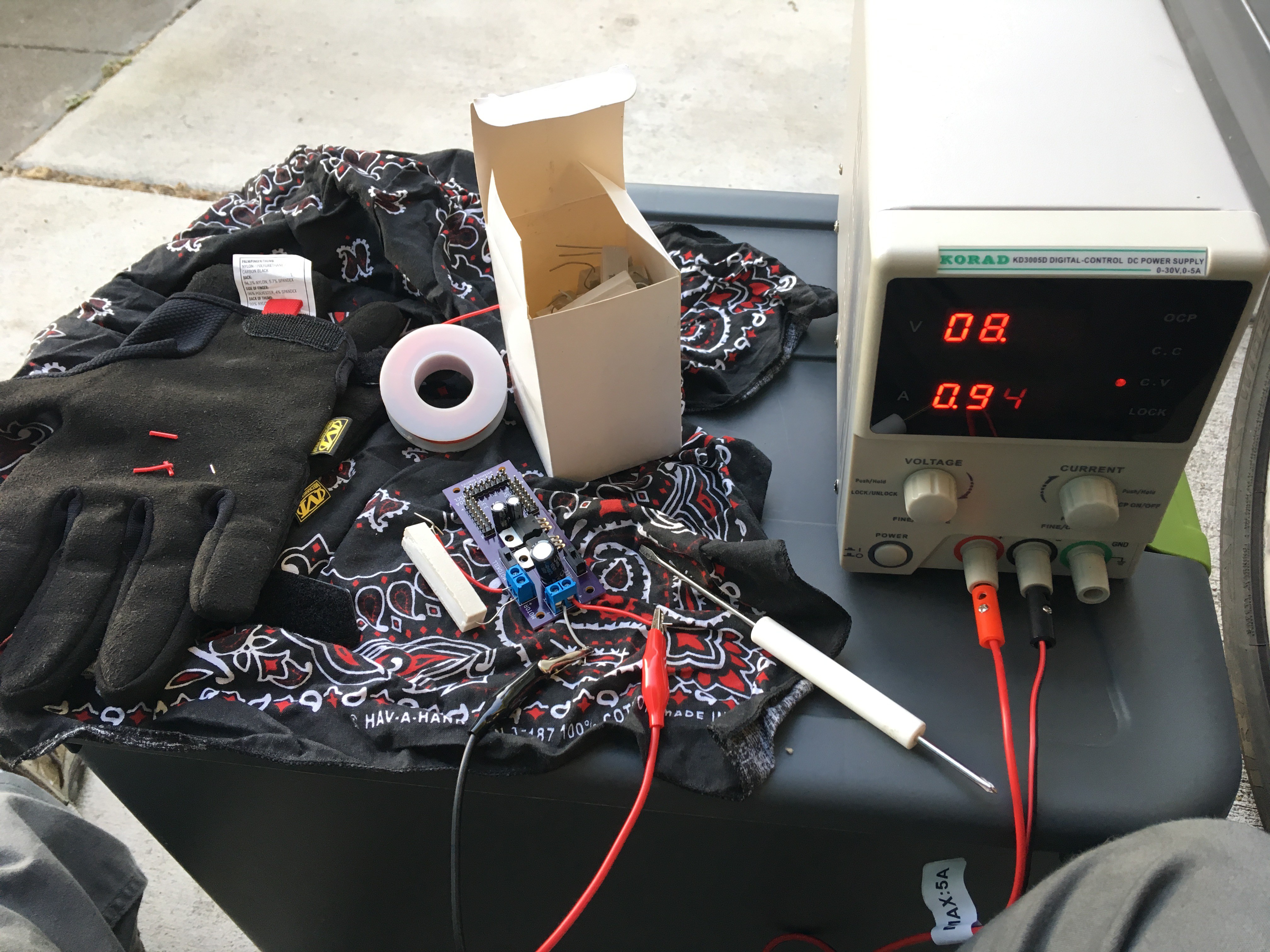
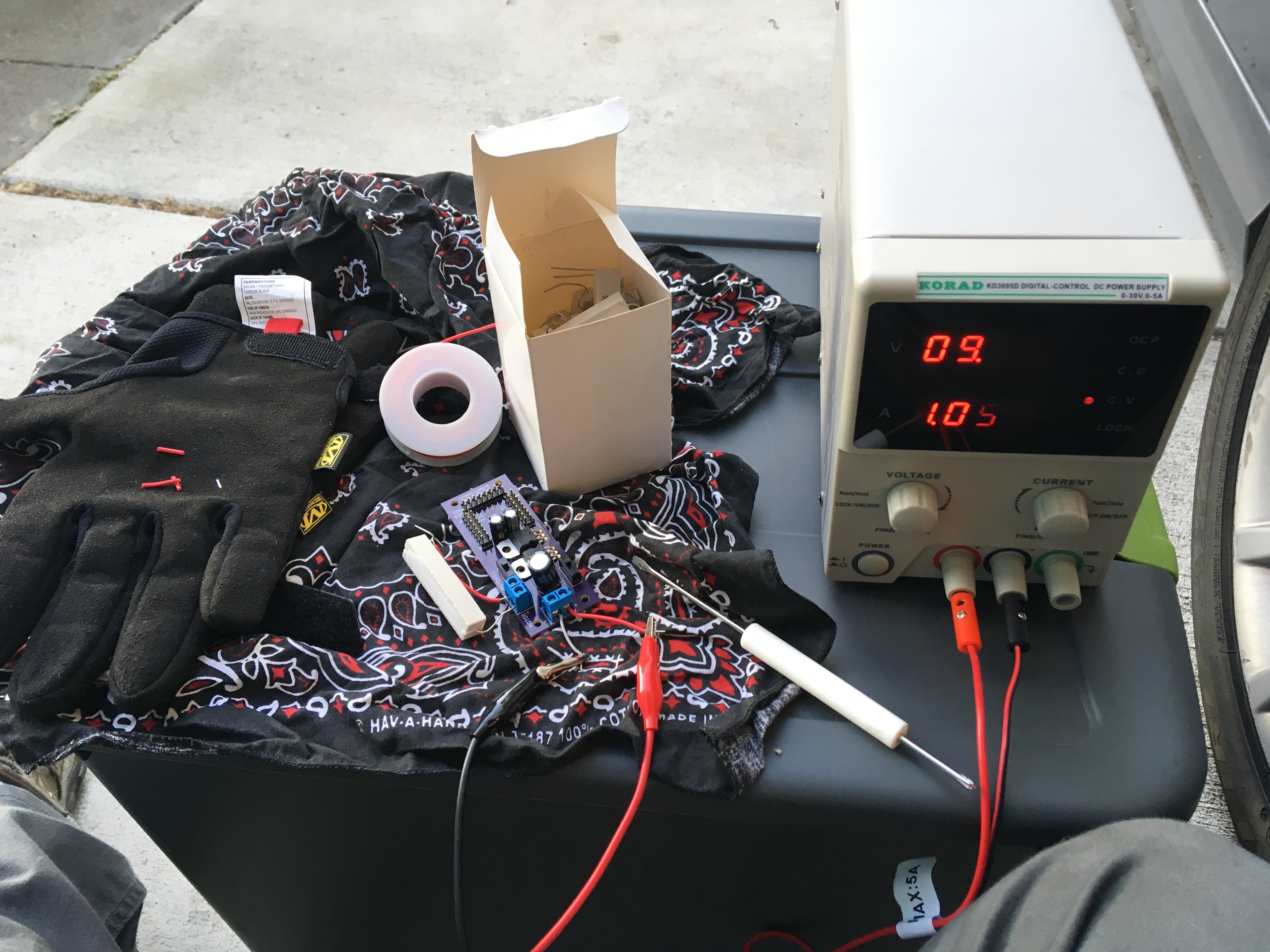
I'm leaving the input power flexible; I have some 2x18650 battery packs (~8V), some 4xAA battery packs (6V), some 5xAA battery packs (7.5V), and 6xAA battery packs (9V).