Close
0%
0%

Симон

The old "Simon" memory game.... with an evil twist

Similar projects worth following
Starting from
$79.95
nsayer has 2293 orders / 162reviews
Ships from United States of America
If you haven't ever seen or played "Simon," go read about it at Wikipedia: https://en.wikipedia.org/wiki/Simon_(game) Simon done the "normal" way has 4 buttons each with its own color (blue, green, red and yellow). The colors are sort of molded into oversized buttons, so the relationship between the buttons and the color sequences in the game is immutable.What if that wasn't so? What if the buttons were essentially clear with 4 color (well, really three, but yellow is green+red) LEDs? You could then make Evil Simon (aka Симон), where you still had to match the colors, but the colors could appear on *any* button. The name of this project is "Симон," which is just Simon in Cyrillic script. Because this is the Simon that Vladimir Putin would make.

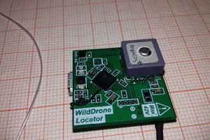
The game is centered around an XMega32E5 controller. This controller is nice because it has a 12 bit DAC and an EDMA engine, which are really easy to use as a digital audio playback system (see also my GPS Talking Clock project). The controller doesn't have nearly enough flash space for audio samples, so to hold them, there is an SPI flash chip. The flash chip has a FAT disk image in it with the audio sample files. There are also 4 buttons and 4 3-color LEDs. The LEDs are in a matrix, where the common anodes are selected by one set of 4 bits and the color cathodes are selected by another 3 bits. There are MOSFET drivers for each to protect the controller. The anodes have pull-downs on them to cut down on ghosting.

The SPI flash chip wiring is fairly perfunctory. It's the one SPI peripheral on the board, so it just gets all 4 of the SPI wires sent directly to it, along with 3.3v power and a bypass cap. Parallel to the chip there needs to be an interface to allow in-situ programming. I've chosen to use the AVR ISP pinout for this purpose, but with !RESET replaced with !CS (which for ISP programming of an AVR really serves the same purpose). Since the controller uses PDI, it's just a lot easier to put two separate headers on the board.

Power for the system is supplied by a pair of AA batteries and a boost converter. The boost converter is the TPS613221A. There is a Schottky diode and snubber circuit in parallel to the chip that is recommended for high current applications (in this case, the audio amplifier can sometimes draw a few hundred mA briefly). The system has soft power control, which starts with a P MOSFET between the battery and the boost converter. The MOSFET gate has two mechanisms to pull it down. First, one output of the controller is an output pin that holds the power on until the software decides to power down. Because the controller has protection diodes to Vcc on its I/O pins, we must isolate them from the !PWR line (which has a pull-up powered from the batteries, and so would potentially be a leakage path). To serve that purpose, there's an N MOSFET that will pull !PWR down when the software outputs a high level on the control pin. But since the MOSFET gate is isolated, there's no chance of power leaking through it. As a bootstrap, any of the game buttons being pushed momentarily draws the pin low, where it will then quickly be held low by the controller (since the boost converter has a bunch of output capacitance we don't have to be too fussy about debouncing the buttons. The caps should be able to easily power the controller long enough for it to pull the !PWR pin on). There are two requirements for this to work. One is that in normal operation, the buttons must be separate to the controller, but any of them should be able to power the system on. Secondly, again because of the controller protection diodes, we must insure that there's no potential leakage path from the P MOSFET gate line. To do this, each button has a common cathode diode array. One anode of each goes to the !PWR line, the other to its I/O pin of the controller. The diodes in front of the controller pins block any potential leakage, and the other diodes isolate each switch from each other despite the common ability to pull down on !PWR when pushed. In order for this system to be reliable, the brown-out detector of the controller needs to be set up. Otherwise, as the power dies it can cause spurious RESETs, and the first thing the firmware does is turn the power on. With a proper brown-out detector, as the voltage falls, the controller is held in RESET with hysteresis to prevent that from happening. The BOD threshold is 2.8 volts because the safe area for the XMega32E5 at 32 MHz bottoms out at 2.7v.

The DAC output is fed into an LM4871 push-pull audio amplifier. It's more or less straight from the datasheet. There is an extra cap in parallel with the feedback resistor to give a little...

Read more »

Adobe Portable Document Format - 91.65 kB - 10/05/2019 at 23:50

Preview
Download

sch - 244.97 kB - 10/05/2019 at 23:49

Download

brd - 114.91 kB - 10/05/2019 at 23:49

Download

  • 1 × Board with SMD components mounted (see schematic)
  • 1 × Keystone 2462 2xAA battery holder
  • 1 × Speaker shelf (3D printed part)
  • 2 × #2 x 3/16 trumpet head self-tapping screw Electronic Components / Misc. Electronic Components
  • 1 × Cui CLF0381MP-1 speaker

View all 8 components

  • Sound design

    Nick Sayer11/21/2019 at 21:58 0 comments

    It's a small detail, but I think it's worth talking about briefly.

    Simon is an audio-visual game. Each button has a color and a sound associated with it (that Симон abuses that rule doesn't change it). In the original Simon, the four sounds made a major chord (with the 4th note being an octave above the lowest). That made for happy sounds. Even recent Simon models use major triads for their sounds.

    Симон, however is evil. So in keeping with its evil nature, the sounds are a diminished 7th chord. Each tone is a minor third away from its neighbor. It's the same chord (type) as the (in)famous Apple "sosumi" system sound. The four individual notes are C, E♭, G♭, B𝄫.

    The sounds were made with GarageBand using a particularly pretty sounding chime instrument.

  • Yet another evil twist

    Nick Sayer10/07/2019 at 18:16 0 comments

    RGB LEDs can assume one of 7 colors (assuming that the anodes are either fully on or off, and not counting "black", which is just all of them off). To date, Симон only uses 4 of them - red, green, blue and yellow. Another way to screw with the player is to change the game's palette at the start of every game to pick four out of those seven. So a game might be in cyan, yellow, magenta and white for example.

    This might be going a step too far. I'm undecided. But at least on a hardware level it's certainly possible.

    That said, I don't want to turn Симон into a 5+ button game. Going to 5 buttons would be doable without major changes, but 6 or more would require putting the buttons in a matrix and it just gets a lot more complicated and begins to stop honoring the original legacy of Simon (which is a nice way of saying "stealing the look and feel").

  • Battery test

    Nick Sayer09/23/2019 at 18:02 0 comments

    Since the XMega has an ADC and we're not using it for anything else, we do have the opportunity to use it to test the battery state.

    The XMega ADC is the weak spot of the chip. The ADC is, in general, buggy and noisy. But this application isn't very demanding, so it's ok.

    One issue with the ADC is that the highest internal reference available is Vcc/2, which isn't high enough to measure the incoming battery voltage. So we have to connect the AREF up to Vcc to get a reference comfortably above the battery voltage. The battery voltage goes to pin A1. We configure the ADC for signed differential conversion with 4 times oversampling. This gives us an effective unsigned 11 bit range (the entire negative range of the ADC gets thrown away by pinning the negative differential input to ground). All we really need to do is occasionally compare the ADC reading to a threshold and give a low battery visual indication and shut down whenever it's low. Since the system reliability threshold is somewhere between 2.1 and 2.2 volts, we'll just figure out what value works out reliably to be around 2.2 volts and give that a little cushion and call it a day.

    EDIT: I've tested this now on a prototype by tying AREF to AVcc and A1 to the battery sense spot (immediately south of the power MOSFET). A threshold reading of 1550 works on that one. As soon as boards come back that have these connections wired in, we can test for variance to see how repeatable that value is. It'd suck to have to somehow customize each unit on the assembly line. Hopefully that sort of nonsense won't be required.

    EDIT 2: Actually, using the analog comparator is easier and better than using the ADC. It doesn't require the AREF connection, has hysteresis, and the test is just checking a single bit in a register.

  • Case design

    Nick Sayer09/21/2019 at 14:32 0 comments

    Work has begun on a 3D printable case for Симон. The case comes in 7 pieces - a front piece, 4 buttons, a back and a battery door.

    The front has four arc shaped cut-outs for the buttons, much like original Simon does. The center is liberally perforated with holes for the speaker.

    The buttons have a small rim that keeps them from falling out. Each also has two long posts that come out from the bottom near the far edge that will rest on the PCB and keep the buttons from falling inward. The two will form a pivot that will allow the front part of the button to move inward where another post will rest on the tactile switch on the PCB. The hope is that this will allow the button to be pressed easily. The buttons are 1/16" thick throughout and when made with translucent resin should easily show the color of the LED underneath.

    The front has two posts that rise up to meet the PCB right where there are two holes. Those holes will accept screws through the board and matching risers in the back panel. Two screws through the back panel, PCB and into the front panel posts will hold the case together. The back is mostly empty space to accommodate the battery holder. Above the battery holder is an empty hole slightly larger. The hole will accept a cover plate held in place with lip edges and a single screw. Overall the case will be a 4 inch diameter circle and be about an inch and a half thick.

  • Build report - 1.3.1

    Nick Sayer09/20/2019 at 21:53 0 comments

    Hardware version 1.3.1 works perfectly so far as I can tell. If I had a complaint it's that the audio volume is a little low. It turns out it's the fault of the low-pass cap on the amplifier feedback. Changing it form 2200 pF to 1000 pF fixed the problem. I did also bump up the feedback resistor from 20 kΩ to 56 kΩ. That boosted the volume a little bit, which will probably be about right for when the board is installed in the case. Also, increasing the anode pull-down resistors from 10 kΩ to 100 kΩ didn't result in the ghosting coming back. On the scope there's just a little bit of a tail still at turn-off, but it's just a little less wasteful now when the anode is switched on.

    The power problems are all solved. The gate of the power MOSFET is effectively right at battery voltage, and I can't find a mA of leakage from the batteries. As before, the whole system seems to operate just fine at 2.3 volts and starts to flake out at 2.2 volts (from my bench supply). Of course at that voltage it's drawing something like a quarter amp, so if the batteries are that tired, they probably won't keep up in any event.

  • Next steps for soft power.

    Nick Sayer09/09/2019 at 07:20 0 comments

    It looks like to solve the soft power problem I need to take some more extreme measures to isolate the soft power system from the controller.

    In the previous attempts, two BAT54As were used to allow any of the buttons to drag !PWR low. Unfortunately, this also creates a path from the pull-up resistor on the soft power MOSFET through the controller pins and their protection diodes to Vcc.

    The fix for that is going to be to give each switch a BAT54C instead. One leg of each array will pull the controller pin low and the other will pull !PWR low. A side effect of this arrangement is that it breaks the path from !PWR to the controller pins.

    Breaking the connection from the controller's !PWR pin requires adding an N channel MOSFET. The software will now instead pull the respective pin high instead of low, which will turn on the N MOSFET and drag !PWR low.

    This is going to be v1.3.1, and it's on order from OSHPark now.

  • Build report - 1.3

    Nick Sayer09/09/2019 at 03:48 0 comments

    Well, the short version is that v1.3 works perfectly.

    The new boost converter doesn't seem to have any trouble powering the game, at least with fresh batteries. Some testing with reduced voltage is pending to see how far that goes.

    The audio crosstalk is gone, now that the DAC line doesn't go near any of the LED rastering lines.

    I've made a couple of small improvements and now ordered a 1.3.1 board. That likely will go into the Tindie store once it's arrived and verified.

    So... now there's nothing to do but get on with the case design.

    Speaking of that, the speaker shelf is a failure, unfortunately. The threaded inserts don't fit. I'll have to iterate that design and try again.

    UPDATE:

    Well, there are some things that need validation.

    The system operates normally down to 2.3 volts, then loud audio makes it unreliable. The question there is whether that's acceptable or not. Hopefully it is.

    The other issue is that the soft power system is unreliable. When off, there's enough leakage to make the LEDs turn red. The soft power MOSFET gate is something like 2.mumble volts even with a 1kΩ pulll-up resistor. Clearly something has to be done about that.

  • Penultimate steps

    Nick Sayer08/24/2019 at 00:08 0 comments

    Right now the prototype suffers from two distinct problems. One is that there's some crosstalk of the LED rastering on the audio. That I believe I can solve by simply routing the audio line so that it doesn't cross under any of the raster lines. The other is the audio amp power issue I alluded to in the last log.

    I've put in two designs for the next round of fabrication, and selecting between the two will be likely the last design change before a board-only product is ready.

    One choice is to power the audio amp directly from the battery, leaving the boost converter to solely power the logic system. This is a bit dissatisfying to me, as the idea is that the whole system should get constant, steady power until it the batteries are "exhausted" and then it should just stop. A steady decrease in the battery voltage is going to mean that the audio will degenerate slowly over the battery lifetime. That said, in testing (albeit with fresh batteries), this resulted in completely glitch-free software. This is v1.2.4 in the Files section.

    The other choice is switching to a beefier boost converter. The next candidate is the TPS613221A, which can supposedly make upwards of 500 mA (at a battery voltage of 2.5v), if I'm interpreting their charts correctly. In addition, the datasheet suggests that for high current applications, you place a Schottky diode in parallel with the controller, at which point the controller's sole job is to switch the inductor into and out of its charging configuration. This is v1.3 in the Files section.

    We'll have an answer in two weeks.

    EDIT: Another possible way to go is to use the TPS613222A boost converter to make 5 volts for both the audio amp and the LEDs and use a 3.3v LDO to power just the controller and flash ROM. This is essentially the same power configuration as the GPS talking clock, so I have increased confidence that it would work. The problem is that it's going to likely dramatically increase battery consumption with little real benefit. This would also require some minor software tweaks, as we would have to use an open-drain for switching the LED anodes off and on - the "off" voltage would be 5 volts, which the controller can't supply (a pull-up would be used instead). This just means switching the data direction lines instead of the output lines (with the outputs pre-set to 0).

  • 2nd prototype build log

    Nick Sayer08/22/2019 at 21:56 0 comments

    The second prototype build was more or less successful. The one problem remaining to solve is the impact the audio amplifier has on the 3.3 volt power rail.

    47 µH of inductance followed by 47 µF of capacitance feeding the amp didn't fix it. I'm not sure where to go from here.

    One minor detail is that the controller's brown-out detector needs to be configured or else the soft power system becomes unreliable. As the system power drops to the point where the controller is unreliable, it can result in spurious resets, and a reset will cause the power pin to be pulled low (by software). The brownout system has a threshold higher than the chip's minimum and has hysteresis. It's no big deal - just an extra step for programming to set the proper fuses.

    EDIT:

    Well, I have a couple of choices as to what to try next to solve the power problem. One tack is to power the audio amp directly from the battery. This means that it won't be getting a well-regulated supply voltage, and the audio quality will suffer as the batteries drain. But in testing with the prototype, doing it that way does make the system reliable. The other option is to try to go with a beefier boost converter. The nominee is the TPS613221A. It can supposedly provide a bit more current, particularly when configured with an external "helper" Schottky diode. I think I'm going to put in orders in to OSHPark for both options, build them both, and see which works best.

  • Mounting the speaker

    Nick Sayer08/22/2019 at 03:13 0 comments

    The current design for Симон is a 3.5" circle. I believe I've figured out how to get a speaker on it.

    This speaker has a double-sided sticky foam pad on the bottom. The trouble is that in the center of the board, where you'd want the speaker to mount, there's a bunch of stuff that gets in the way - the audio circuitry in particular is there, and it's going to possibly overheat if it's buried under sticky foam tape.

    The solution is a 3D printed little plastic "table." The table has two small risers spaced the same distance apart as the screw holes for mounting the battery holder. By inserting threaded split-wedge inserts in the risers they can act as the nuts for the screws that hold the battery holder in place on the back of the board. The opposite side of the surface from which the risers descend is a "table" upon which the speaker can be mounted. It will wind up being 3/16" up from the component side of the board, which still means the leads will reach the holes on the board, and the back of the "table top" is still 1/8" up from the component side, which is plenty of space to fit all of the stuff underneath.

    I'll add the "speaker table" STL file to the files section of the project.

View all 15 project logs

  • 1
    How to play

    Press any button to power Симон up. The LEDs will pulsating. This is the Attract mode. If you do nothing, it will timeout eventually and power off. Your choices are:

    • Green: easy - decadent Western Simon (i.e. normal Simon)
    • Blue: harder - the sounds will no longer be keyed to the color
    • Yellow: hardest - the positions will no longer be consistent with the color
    • Red: nightmare - when it's your turn, your button colors will also shift around each round
    • Black: impossible - when it's your turn, your button colors will shift around for each step

    To select "impossible" mode, press two (or more) buttons at once.

    Gameplay is simple. Remember the colors Simon shows and repeat the colors back. Get it wrong and you lose. Take too long and you lose. If you can go far enough, you'll eventually win, but I strongly suspect that it's not humanly possible.

    Sometimes Симон will show two buttons/colors at a time. When it's your turn to repeat, for that step you must push both buttons/colors simultaneously.

    To clear the high scores, start with Симон powered off. Press and hold two buttons. All lights will start to blink. Hold the two buttons for ten seconds and the lights will change to the normal pre-game fade in and out. At that point the scores are cleared and you can let go of the buttons. 

  • 2
    Building

    There's no special instructions for installing the surface-mount components. Obviously, make sure all of the LEDs and ICs are installed facing the right direction.

    You should program the controller and flash ROM before attaching the AA battery holder and speaker, as the speaker will get in the way of the two programming headers.

    To create the SPI flash disk image (this procedure is for Linux and is for a 4MB chip):

    • dd if=/dev/zero bs=4M count=1 | tr '\0' '\377' > image
    • mkfs.vfat image
    • sudo mount -o loop image /mnt
    • cd /mnt && unzip sounds.zip
    • sudo unmount /mnt

    The firmware doesn't care how big the flash chip is as long as the "0x03" read command works and the chip is large enough for all of the samples. As a rule of thumb, each megabyte of space can hold about a minute of audio. It's best to start with an image file full of "FF" bytes, as that make the programming go much faster (FF is the default erased content of flash ROM).

    Program the SPI flash chip first. If the controller is programmed, then it must be held in RESET or erased while programming the flash chip to insure the SPI bus is kept quiescent. The FLASH programming header has the same pinout as the traditional AVR ISP pinout, with !RESET being replaced with !CS. The easiest way to program the chip is to wire up a Raspberry Pi to do the job. Connect 3.3v power and ground (pins 1 and 6), the MOSI, MISO and SCK and SPI_CE0_N pins (pin 19, 21, 23 and 24) up to the programming header. Use raspi_config to enable SPI and reboot, then install "flashrom" and use it to program the image (-p linux_spi:dev=/dev/spidev0.0,spispeed=20000)

    Compile the firmware with an avr-gcc compiler and link with avr libc. Program the result into the controller with avrdude and a suitable PDI capable programmer connected to the PDI header.

    Also, set fuse5 to 0xe9 to program the brownout detector. For extra credit, seed the PRNG by filling the first 16 bytes of eeprom with random bytes.

    Note that neither the flash programming header nor the PDI header are 5 volt tolerant. Use 3.3v only! If your PDI programmer cannot provide target power, you can force the boost converter to supply power by holding down (or shorting) one of the buttons during programming.

    The AA battery holder mounts on the back of the board. Screw it down using a pair of 4-40 1/4" trumpet head bolts. The bolts screw into threaded inserts that go into the "speaker table" piece. The speaker sticks onto the "speaker table" with an adhesive pad that comes with the speaker. Make sure you orient the speaker so that the speaker wires go into the holes on the board.

    The speaker wires are soldered to their holes. Note that because the amplifier is a push-pull design, neither speaker wire is grounded. 

  • 3
    3D printed case

    Print the top, back and battery lid in opaque material (black is traditional). Print 4 of the buttons from transparent or translucent material.


    Drop the buttons into the holes from the back of the top piece. Lay the board on top with the keying boss in the big hole. Lay the back on top, lining up the screw holes. Secure the two together with two #4 pan head self tapping screws. 

    Insert two AA batteries in the battery holder. Insert the tab of the battery lid into the short side of the hole in the back that doesn’t have the arch. Lay the lid down so that it fits flush. Screw it down with a #2 3/16” pan head self-tapping screw.

View all 3 instructions

Enjoy this project?

Share

Discussions

danjovic wrote 09/23/2019 at 01:15 point

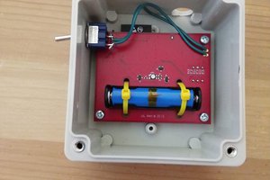
Insanely awesome idea!!

  Are you sure? yes | no

Nick Sayer wrote 09/24/2019 at 19:57 point

Thanks! Having played it, it's really, really challenging. My wife predicts many of them will be destroyed in fits of rage. :D

  Are you sure? yes | no

Similar Projects

Does this project spark your interest?

Become a member to follow this project and never miss any updates