 Matthias Koch
This one starts up at 150 mV and reliably resets the MSP430F2012. It's a blocking oscillator using a black and white television flyback transformer and seven BF245A JFETs in parallel for getting enough loop gain to start oscillations. The 20 kOhms are necessary as the gates conduct in reverse, and I wish to use the energy for the microcontroller instead. Then, the high voltage winding of the flyback feeds directly into the /Reset pin of the microcontroller. The two 100 nF capacitors form a voltage doubling rectifier together with the protection diodes of the /Reset pin. I latter added BAT85 shottky diodes to reduce the voltage drop for startup at lower voltages. The blue LED together with a normal diode acts as a "shunt regulator" for overvoltage protection if the microcontroller does not dissipate the energy.
Because of clipping, the oscillator delivers a roughly square shaped waveform between 2 kHz and 4 kHz (depending on solar cell power) into the /Reset pin. The microcontroller now has enough time to boot during the high part of the cycle, and immediately switches the function of the /Reset pin to NMI input, disabled. Then it switches its clock tree to the internal VLO at 12 kHz further divided down by /8 to 1.5 kHz which is delivered to P1.4 clock out special function, shown on the green LED. The wiggling on P1.0 is just a debug signal for watching with oscilloscope.
Every brownout will re-enable the reset function, therefore, this starts up reliably.
With a different winding on the flyback transformer, I got 40 mV oscillator startup voltage, but I got no useful output current with that. With the winding leading to 150 mV startup voltage, I get enough current to drive the LED and add something useful soon.
The source code is in Forth and can be compiled using Mecrisp-Across:
new

\ <><><><><><><><><><><><><><><><><><><><><><><><><><><><><><><><><><><><><><>
    TARGET
\ <><><><><><><><><><><><><><><><><><><><><><><><><><><><><><><><><><><><><><>

: osc ( -- )

   17 p1dir c!

   1 p1out c!
   0 p1out c!

   $5A80 1 5 lshift or $120 !  \ Watchdog on hold, Reset --> NMI, which is still disabled

   1 p1out c!
   0 p1out c!
   1 p1out c!

   0 DCOCTL c! 0 BCSCTL1 c! %11111110 BCSCTL2 c! %00100000 BCSCTL3 c!  \ VLO/8, Clock out 1.5 kHz

   16 p1sel c!

   begin lpm1 again
;

\ <><><><><><><><><><><><><><><><><><><><><><><><><><><><><><><><><><><><><><>
    HOST
\ <><><><><><><><><><><><><><><><><><><><><><><><><><><><><><><><><><><><><><>

$FFFE vector osc   crosscompile

disimage-file jfet-wiggle-nmi.asm
 hexdump-file jfet-wiggle-nmi.hex

 Jan Waclawek
 Yann Guidon / YGDES
 Muth
Muth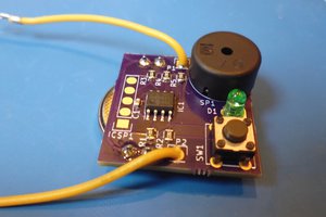
 Jose Ignacio Romero