Close
0%
0%

Data logger device for DM3058 digital multimeter

Small device that connects to serial port of DM3058 bench top multimeter to retrieve and log measurements

Similar projects worth following
Goal of the project is to create measurements logger device for Rigol ® DM3058 bench top multimeter. Data logger connects to serial port on DM3058 to retrieve measurements. To open measurement files data logger is connected to computer as USB flash disk.

Such device is useful for those who need to run measurements at known intervals and analyze the results. It significantly extends measurements logging possibilities of DM3058 multimeter as it expands measurements memory and allows to quickly retrieve logged measurement sessions.

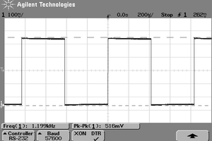
Rigol ® data logging software exists but is not for free. Although other software based solutions are possible they are quite unstable and require having software running on computer while measurements are logged. DM3058E being entry level model lacks more advanced connection interfaces, built in data memory is limited as well. DM3058E has, however, 9-pin serial port and command set. Serial port on this muiltimeter can pass trigger and data ready signals. By utilizing serial port I set out to create measurements logging device for my own needs and then extend it towards completed device.

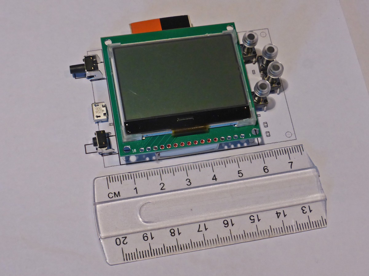
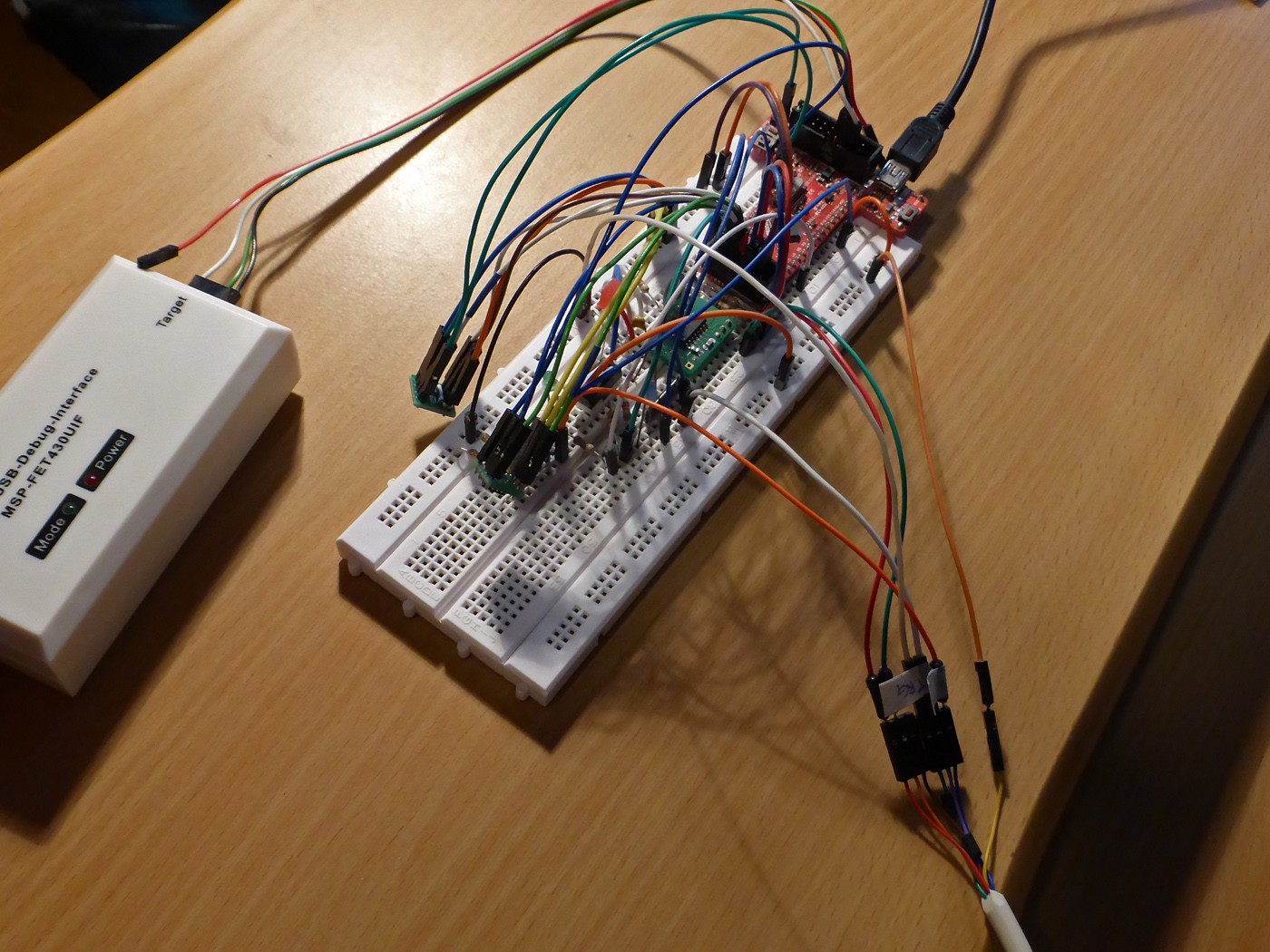
Device is based on Texas Instruments ® MSP430F5510 micro controller. Queried measurement data is saved in SPI flash. 520 K measurement records can be logged and retrieved from device as csv text files. Additional SPI EEPROM is used to store disk partition, file records and file allocation table information while connected to computer as USB mass storage device.

Measurements triggering rate can be set in range from tens of milliseconds to 120 seconds. DM3058E is somewhat limited in its ability to set exact timing of measurements. Two distinct data logging modes (interval and continuous) are used by the data logger to accommodate both long and short measurement periods. Continuous mode adjusts to measurements clock of the multimeter and makes possible to retrieve measurements at fast and uniform rate.

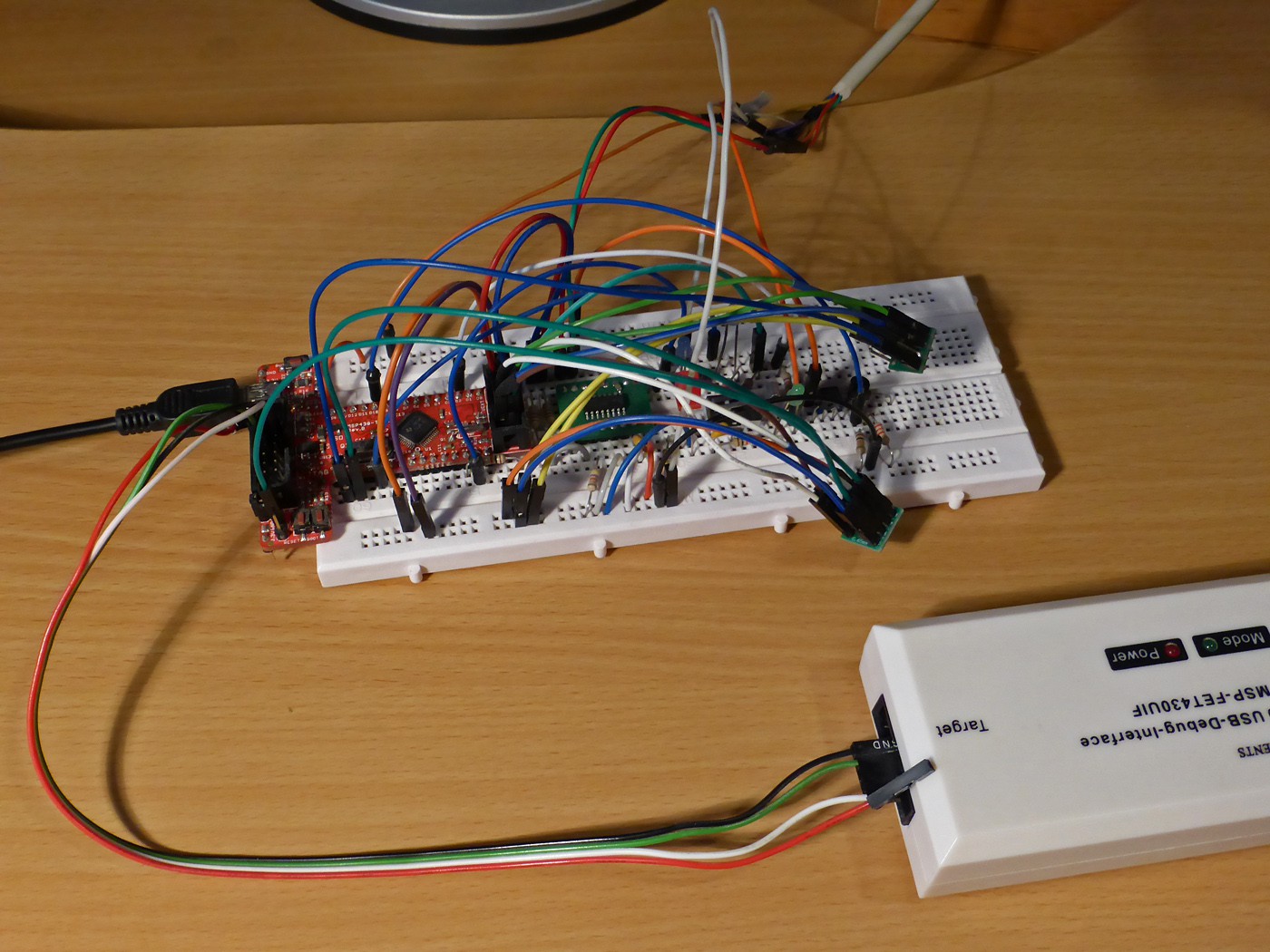
Firmware of the device for the device was developed using Code Composer Studio. Code does not use any external libraries except for MSP430 Driver Library and MSP430 USB Developers Package code that is licensed under Modified BSD License.

It would also be possible to adapt data logger for other multimeters like Tektronix DMM4020 or “classic” HP/Agilent 34401A. There is custom firmware to use the data logger with DM3068 multimeter that was created with the help of DM3068 user in Germany. Even if DM3068 has larger built in data memory to log something exact and save it to USB flash is not very straightforward using built in controls.

There are several users of the data logger device in Germany, Australia and United Kingdom. Devices assembled at the moment are listed on Tindie. User manual and sample data logs formatted in Excel are in files section.

dm3058_logger_manual.pdf

Data logger manual

Adobe Portable Document Format - 288.01 kB - 05/17/2021 at 09:29

Preview
Download

dm3058_sample_logs.xlsx

Measurement logs nicely formatted in Excel

sheet - 965.36 kB - 03/13/2021 at 16:02

Download

  • Firmware update for USB disk mode

    Krists05/17/2021 at 09:33 0 comments

    USB disk mode function was updated so that data logger can stay connected both to multimeter and computer at the same time. USB disk with logged measurement files can be disconnected and reconnected using controls without unplugging and re-connecting tiny micro USB connector all the time. This allows to quickly read measurement logs and re-run measurement session again.

    User manual file was updated to show new functionality.

  • Enclosure and device update

    Krists10/12/2020 at 16:43 0 comments

    Device now has user manual and enclosure got rubber boots so it stays still on table. Data loggers listed on Tindie come in superb quality black SLS printed enclosure.

    Another video shows how data logger might be used.

  • 3D model of the enclosure

    Krists06/20/2020 at 15:52 0 comments

    3D model and print of the enclosure for the device is ready. Small changes should be made but overall everything fits together nicely. One catch, though, is that ABS material used for print is quite translucent and backlight from LCD screen illuminates through the material. This could be fixed by using additional light blocking insert or making front part thicker and having less translucent material.

    Read more »

  • Data logger prototype demo

    Krists05/30/2020 at 07:15 0 comments

    Here comes video that shows existing functionality of data logger prototype.

    It shows how measurements logging works and how measurements data files can be opened by connecting data logger to PC as USB flash disk.

    Measurements are logged in two modes. In “interval mode” data logging rate is set in seconds, this would be useful to capture some lengthy process. Measurements are requested at this interval. As described in previous post measurements might not be taken at that exact time. “Continuous mode” measurements run at the rate that depends on multimeter measurement mode. It is not possible to change that but by logging one measurement and skipping some known number of measurements it is possible to achieve somewhat stable and changeable measurements rate. This would work for capturing measurements of some fast changing process. In video it shows how measurements of 0.5 Hz sine wave signal can be captured this way.

    Data logging works for dual mode measurements as well. It is shown in second part if the video. Dual mode measurements - logging changes to both voltage and current was main reason why I got interested in DM3058 multimeter.

    It did take a while to get so far. There are, however, more issues to be fixed.

  • Rigol tech support (un)response

    Krists09/26/2019 at 04:14 0 comments

    While testing measurement recording I realized it is not really possible to read data at exact short intervals using external triggering mode. Sampling rate for DM3058 ranges from 400 ms in SLOW reading rate to 8 ms in FAST reading rate. But in case of external triggering it does not mean that measurement is done exactly at external trigger pulse. It seems that sampling runs on its own internal clock and on external trigger pulse multimeter just returns value of measurement that it currently is sampling. But it does not correspond to exact time when trigger pulse was sent. It does not really matter for logging lengthy battery discharge curve every few seconds or so. But it seems not possible to accurately log measurements anywhere close to sampling rate of DM3058.

    I decided that for short intervals I might try using use internal triggering mode of multimeter and read out measurements when they are ready. It is possible to set custom internal trigger period in the range from minimum sampling time up to 2000 ms. But as I found out internal trigger period of the multimeter is not accurate either, not at least on my device. In fact it does not trigger at exact interval that is set using menu or serial command. Measurement triggers at some other time period that most likely depends on internal software or hardware constraints. I tested it with measuring slowly changing sine wave voltage at various intervals and different measurement rate modes. Sine wave period was fixed to 2 seconds. By saving built in measurement history (up to 2000 readings on DM3058) to USB flash I examined voltage wave forms using excel graph. I checked how many measurements were taken over one full sine wave period. I found out that while some trigger interval settings were logged as expected, most of them did use some other interval value that did change with selected measurements mode.

    Read more »

  • Controls and pcb layout

    Krists08/09/2019 at 12:32 0 comments

    Having schematic seemingly working on breadboard it was time to move on to PCB. This required some decision on layout and controls for the device. Controls would be power on button, recessed firmware upgrade mode button next to USB connector and four controls next to LCD. One for starting and stopping data logging, other for changing trigger period and two more for up down for navigation where necessary. Main PCB would hold all elements and connector for LCD with its own PCB on top. Pig tail cable to serial port of muiltimeter would go on back of main PCB. With controls besides screen this sets form factor for device. Device would stand vertically on bottom edge. It seems that main controls might be operated single handed.

    I opted for standard tact switches with silicone like material caps I sourced from eBay. Enclosure around this layout could be designed and 3D printed. Although it would be great to have front panel overlay it adds to expense and is separate part.

    Read more »

  • LCD display for data logger device

    Krists08/05/2019 at 10:19 0 comments

    Data logger can function without a display, but I realized that having one will make it much more understandable and easier to use. I shopped around for small graphic LCD with white backlight and black text. What I got was Zolen ZLE12864A LCD module from eBay seller in China. Although units with these exact colors were not listed after some discussion I got what I was looking for. Seller was able to look up exact LCD module for me with 3.3V logic level voltage. There is decent datasheet with setup commands and dimensional drawing as well. It has ST7565P controller – although cheap it does not have any font memory built it. Size of PCB will most likely define size of data logger.

    It did take some months to arrive as I did not pay for express shipping. Manufacturing looks very clean and nice. First impression of LCD itself was not so great, though. Regardless of tweaking it has some vertical and horizontal shadows around displayed text and appearance changes a bit depending on viewing angle. But after a while I got used to it. If they look somewhat cheap that’s because they are. I got five for just $6 per item. They will be good enough for initial data logger prototypes. Main bottleneck might be code space and memory needed to operate them.

    Read more »

  • Functional and data logging considerations

    Krists08/05/2019 at 10:05 0 comments

    Initial development on data logger device started sometime by the end of last year. First steps were to test serial commands according to programming manual and see how they can be used. After some tweaking it seemed that correct way would be let data logger to trigger measurement, wait when it’s ready and issue command to read value. All measurements from multimeter are reported as numbers in scientific notation like 1,506540-E10 so that text string is uniform regardless of actual value. To have values meaningful in log files data logger should query active measurement mode as well. Fitting reasonable amount of data in 16-megabit SPI flash requires converting values to binary format. When mounted as USB mass storage logger would decode these records and present them as text files in file system. I had some knowledge on how FAT file system works, but had to do a good refresh. About the X-mass time I was thinking more about FAT entries and partition records that anything else. It was fun time though and I got it working. I was able to built virtual file system on the fly, as there is no real memory available for data in plain text format. It works not very fast, though.

    So it looks that device should have some pig-tail connection to serial port on back of muiltimeter so it can be connected and removed as needed rather fast. I might use RJ45 connector for this. I don’t quite like that locking tab on RJ45 plug is prone to breaking but sockets, connectors and protective boots as well are readily available. I would need just 6 wires for connection. So called British Telecom telephone plug looks like a good choice, but solderable small sized PCB sockets for these are not widely available.

  • Early design decisions

    Krists08/01/2019 at 16:15 0 comments

    From hardware viewpoint device would operate in two modes – first as serial console to DM3058 multimeter and then as USB mass storage device when connected to PC. Early on I decided to use Texas Instruments ® MSP430F55xx micro controller for this task as it has stable USB support in hardware and I had some experience playing around with USB devices on MSP430F5529 LaunchPad board. For data storage I would use SPI flash chip, then I would need RS232 transceiver and some input protection ICs. I wanted to use lowest spec devices still adequate for the task. Parts would be SMD but still suitable for hand soldering, except for switches and alike that would be though hole, at least for first prototype. I ended up choosing MSP430F5510 micro controller for which I could use nicely designed Olimex ® MSP430-T5510 development board and set up rest of schematic on a bread board. For data storage immediate choice was to use somewhat outdated but still available Atmel ® AT45DB161 16-megabit SPI flash IC. I would see where it all will take me. Renesas ® ICL3221 would serve as RS-232 transceiver for connecting to DM3058E serial port. It has single RX/TX pair instead of classic MAX232 dual driver and receiver arrangement. It is also a bit cheaper than other similar ICs and ICL3221E version has somewhat better ESD protection specs on RS232 pins.

    Quite a lot of wiring. MSP430-T5510 development board can be seen in red and RS232 transceiver on breakout board. SPI data flash and EEPROM ics are hanging out on wires.

    To clear any doubts I would not consider device I am working on as a hack of any sort. Serial port specification and data exchange protocol for DM3058E is readily available at Rigol ® website. I am also not affiliated with the company in any way except that I have bought DM3058E multimeter through their product clearance web site.

View all 9 project logs

Enjoy this project?

Share

Discussions

Similar Projects

Does this project spark your interest?

Become a member to follow this project and never miss any updates