 John Lonergan
As one of the modules of my "TTL" CPU caled SPAM-1 I’ve been wiing up the UM245R serial to parallel UART from Future Tech Devices Inc FTDI.
See datasheet :https://www.ftdichip.com/Support/Documents/DataSheets/Modules/DS_UM245R.pdf
I’m using it to provide a convenient way to allow SPAM-1 to communicate with the outside world.
For simulations of my whole CPU I’ve also written a complete Verilog model of the UM245R UART to send data to a graphics terminal I’ve written that runs on my PC and which I will also be able to hook up to the real UM245R once the project is built. https://github.com/Johnlon/spam-1/blob/master/verilog/uart/um245r.v. The verilog model allows remote control of the simulation.
So, I thought I’d share what I’ve learned and I’ll hopefully do a video about the Verilog simulation if I can figure out an approach that makes sense.
Anyway, the first and perhaps only big decision you have with this device is to decide how it will be powered.
Two options:
- Bus Powered where we power the UART and the surrounding project from the USB power
- Self Powered where the surrounding project supplies the power – eg from batteries or a PSU
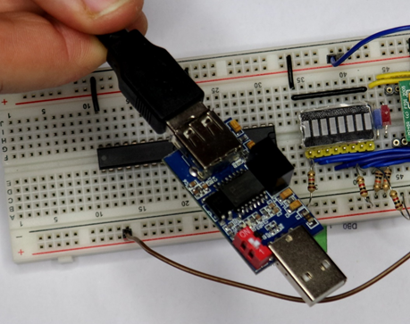
You can see the work-in-progress below in bus powered mode, with some LEDs on the data lines (ignore the two buffer chips which will provide connectivity to the rest of SPAM-1).
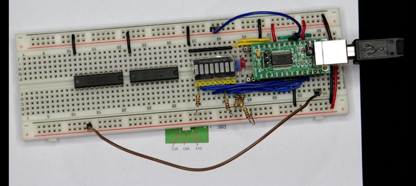
It is wired up in USB "bus powered" mode which is the default it will arrive in.
When you connect the UART to your PC then it will hopefully automatically install the Virtual Com Port (VCP) drivers.
The drivers can be found here https://ftdichip.com/drivers/vcp-drivers/
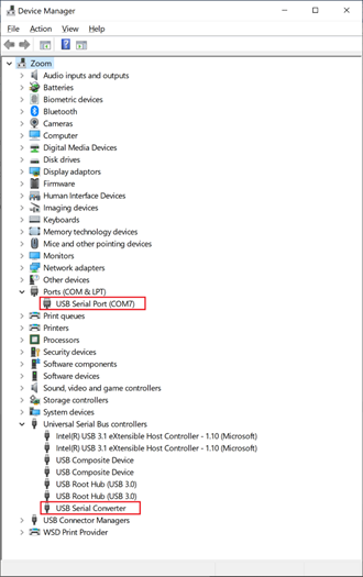
Once you plug in in then the device should appear in Device Manager. On my machine in the ports group and also the serial controllers group.
If you project will run off USB power then you are in luck as that is the default configuration of the device.
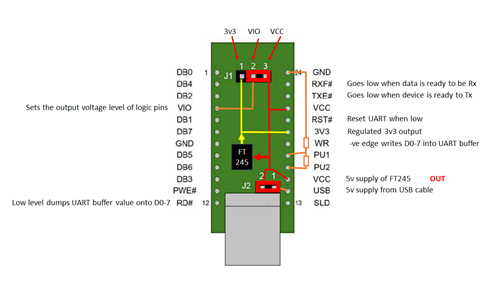
There are a couple of jumper on the board that provide power configuration. if you are going to connect using USB power then you leave these jumper here in the default position which is shown here. You can see here in the data sheet the circuit you'll need for USB power and basically, there is nothing to it.
Since you are powering this UART device from USB the assumption is that you will run your entire project from the USB power.
The UM245R has two signal lines that tell us whether the UART has received data from USB and needs to be read by the project, or whether the UART is ready for data to be written through it back to the PC or whatever its host is.
To communicate with the device you need to monitor the state of two signal lines:
- _RXF indicates whether the buffer in the FT245 chip has received USB data.
- _TXE indicates that the device is ready to accept a byte to send to USB.
Additonally there are RD and WR enable likes and the 8 data pins.
If I want to send data to the USB host (ie laptop) then I need to put some value on the 8 data lines and then bring the WR enable line low. Only do this when _TXE is low.
When _RXF is low then it’s ok to bring RD low to place a received byte on the 8 bit bus.
So, your project simply needs to monitor _TXE and _RXF to device when it’s time to receive or send data and then manipulate the RD/W# lines to execute the send / rcv.
But, I’m not interested in running off USB power for a few reasons…
- It’s inconvenient to have to power the modules via the UART USB during development
- I don’t want to have to connect it to my laptop at all to be honest unless I absolutely need to
- I may want to draw more current than I’d be happy to pull from the laptop – LEDS, EPROMS all add up.
If your project isn't going to run off USB power then you will have your project powered by it's own supply - batteries or whatever
In SPAM-1, my TTL cpu project, I'm going to run it off a 5v breadboard power module connected to batteries.
In this case then we need to look at section 7.2 of the data sheet for the wiring diagram and notes to understand what’s needed.
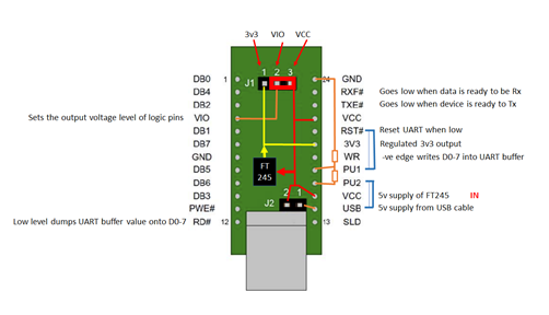
We need to add a link as shown above from the UART’s RST# to PU1, and another link from PU2 to USB which is the 5v coming from the USB cable. The purpose of this wiring is to ensure that the device powers down when the USB cable isn’t connected. The device uses a few 10’s of uA when the UART is in its reset state, but it only uses 15mA when connected. In order to minimise power the circuit diagram is driving the RST# signal from the 5v on the cable in way that when the cable isn’t connected then RST# is held low, but pulled up to logic 1 when the cable is connected. PU1 and PU2 according to the diagram on page 24 are nothing but the terminals of a 50% voltage divider between whatever PU2 is connected to and Ground. So if PU2 as wired to the USB “VBUS” cable power line then when the cable is plugged in then PU1 and therefore #RST will be 2.5v which is logic high and this will take the UART device out of Reset. Alternatively, when the cable isn’t connected then PU1 and RST# will be logic 0 and the device will standby.
EPROM configuration
Section 7.2 also states that the on-board EPROM ought to be changed from the default of “BUS Powered” to “Self Powered”.
Unless you are planning on building a product then I believe this change is actually optional and solely about telling the host what to expect in terms of power demand. It is part of the USB spec to send a descriptor from the USB device to the USB host (the PC) to tell the host what the power demands are. The USB standard says you must do this but to be honest unless you are building a product for distribution then you can skip this step.
Hooking up a serial console
I found using the Arduino IDE’s serial console most convenient to start with, and that’s because that tool tells you which virtual com port is being used by the UART and automatically hooks the serial monitor up to it.
If you know the port then you could switch to putty or whatever tool you like.
But what baud should you use in the serial console?
Well, apparently it doesn’t matter.
https://www.mouser.com/datasheet/2/117/usb245r-ds-v10-14240.pdf says
"By using FTDI’s Virtual COM Port drivers, the peripheral looks like a standard COM port to the application software. Commands to set the baud rate are ignored; the device always transfers data at its fastest rate regardless of the application’s baud-rate setting."
So apparently it doesn’t matter what Baud rate you set the serial console to.
For bits/parity/stop I used “8-N-1”.
Verilog simulation
If you are interested, then I have a realistic Verilog simulation of the device so you can use it in your Verilog projects to send and receive data to the simulation too. I’ve used the U245R simulation in my CHIP-8 emulator test program that runs on top of my simulated Verilog CPU model. This allows the CHIP-8 program to communicate with a simple graphics terminal I’ve written.
UM245R velilog model: https://github.com/Johnlon/spam-1/blob/master/verilog/uart/um245r.v
Demo test program: https://github.com/Johnlon/spam-1/blob/master/verilog/uart/test.v
I’ll hopefully do a separate video on that.
Final Word of Warning
Bear in mind that if you are prototyping you may be taking a risk with whatever you connect your project to like your expensive laptop.
If you have a short anywhere in your project then it will short the USB port of whatever you connect it to. That might hurt your PC, then again it might not, but do you want to take the chance?
I give this warning because I actually did this by accident, and it freaked me out that I might have damaged my laptop.
Windows 10 popped up a scary warning that there had been an over-current on the USB port and said I had to restart the machine.
Thankfully once I had done a restart all was ok - but you might not want to take the risk even if your PC has protection.
Perhaps if you put a powered USB hub in between your project and your precious home computer then that might protect your computer - I dunno.
I've already had one accident I am definitely NOT going to routinely use USB power via this UART in future. In fact, I have bought a USB Isolator to make life a little safer. https://www.ebay.co.uk/itm/293838063896
It is based on the ADUM3160 which uses induction decouplers to make the connection more electrically isolated from the PC host. This device passes at most 200mA and has short circuit protection.
Discussions
Become a Hackaday.io Member
Create an account to leave a comment. Already have an account? Log In.