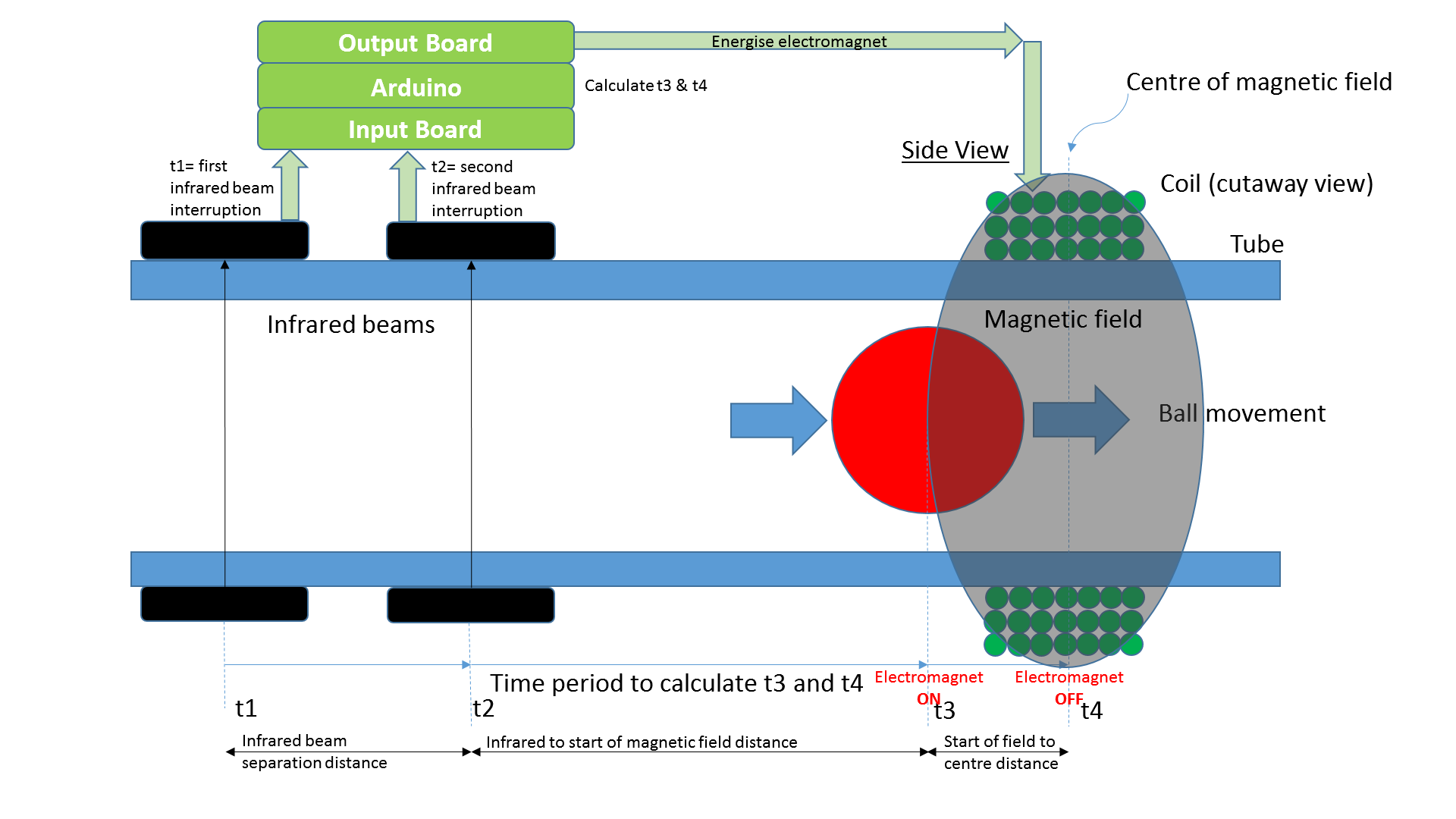
Basic concept
In addition to the hardware interrupts for detecting ball position in the sensors, the Arduino is pushed almost to its limit with various other responsibilities:
- Scanning for input on the 3d printed throttle and associated buttons. These act as a basic input system to change timing parameters
- Displaying speed, timing characteristics and pressure etc on a TFT screen in real time
- Communicating via USB connection to PC. The Processing program on the PC graphs performance in real time
- Optionally controlling additional features, described in Details
The standard size particle accelerator uses an FEP tube around 1m long. FEP is highly transparent and has similar very low friction to PTFE. The next largest size tube up was used to securely align the two ends of the FEP tube to form a loop with almost no discernible join. All electromagnets, and other components slide over the tube.
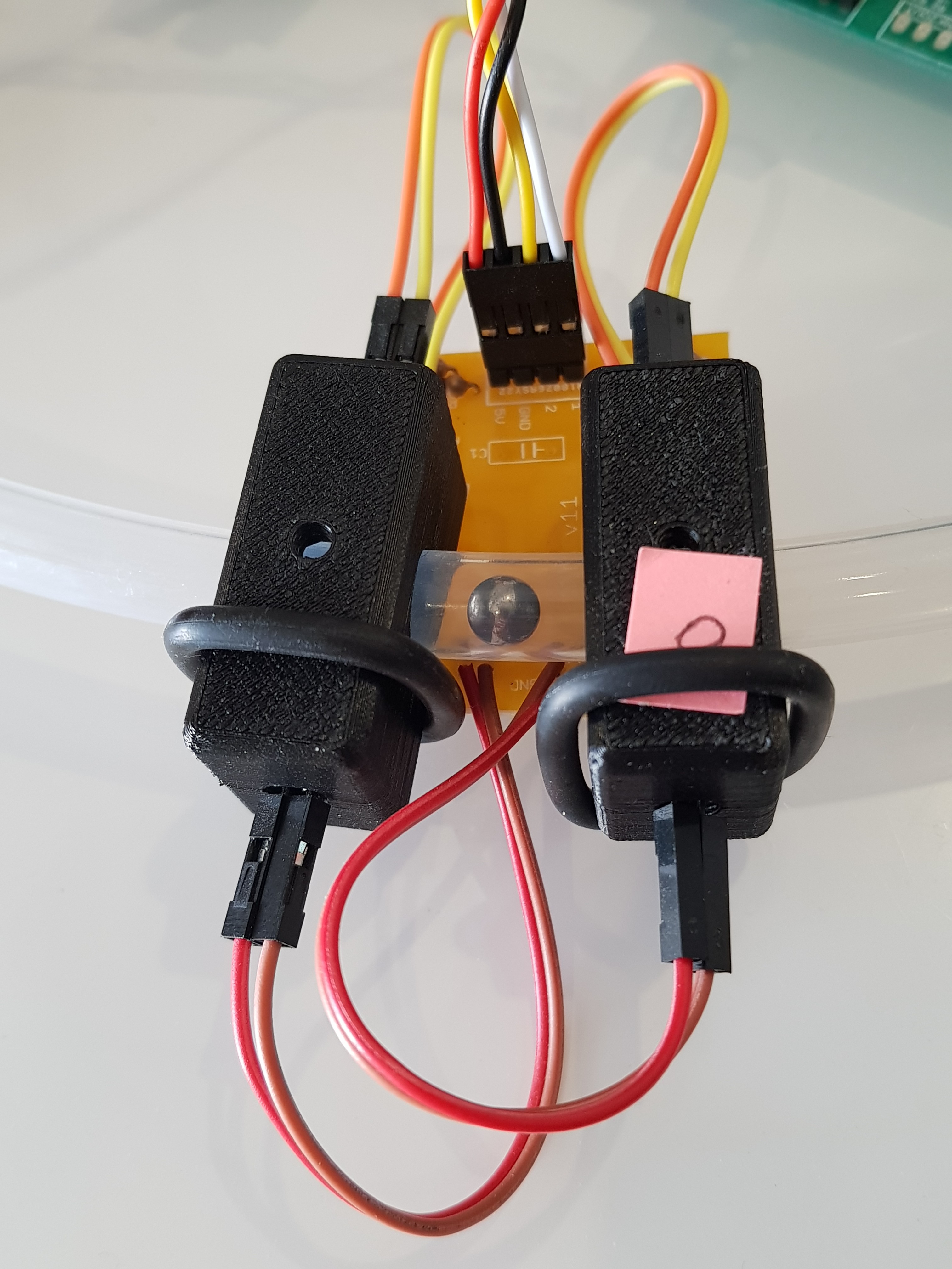
Accurately and reliably detecting the steel ball at high speeds is important. Infrared LEDs and phototransistors were selected for this task, and the output pulse turned into a digital signal via a schmitt trigger. Even at a constant speed, the round shape of the ball could result in different IR beam occlusion durations dependent on the ball's rolling position in the tube when viewed cross-sectionally. For that reason, it was decided to estimate ball speed as the time difference between two fixed point IR beams, rather than the occlusion duration of a single IR beam. The physical housing for the LED/phototransistor pair required many iterations to reliably shield from ambient light, be precisely located, and easily assembled/disassembled. Eventually the following 3d printed half shell design was developed.
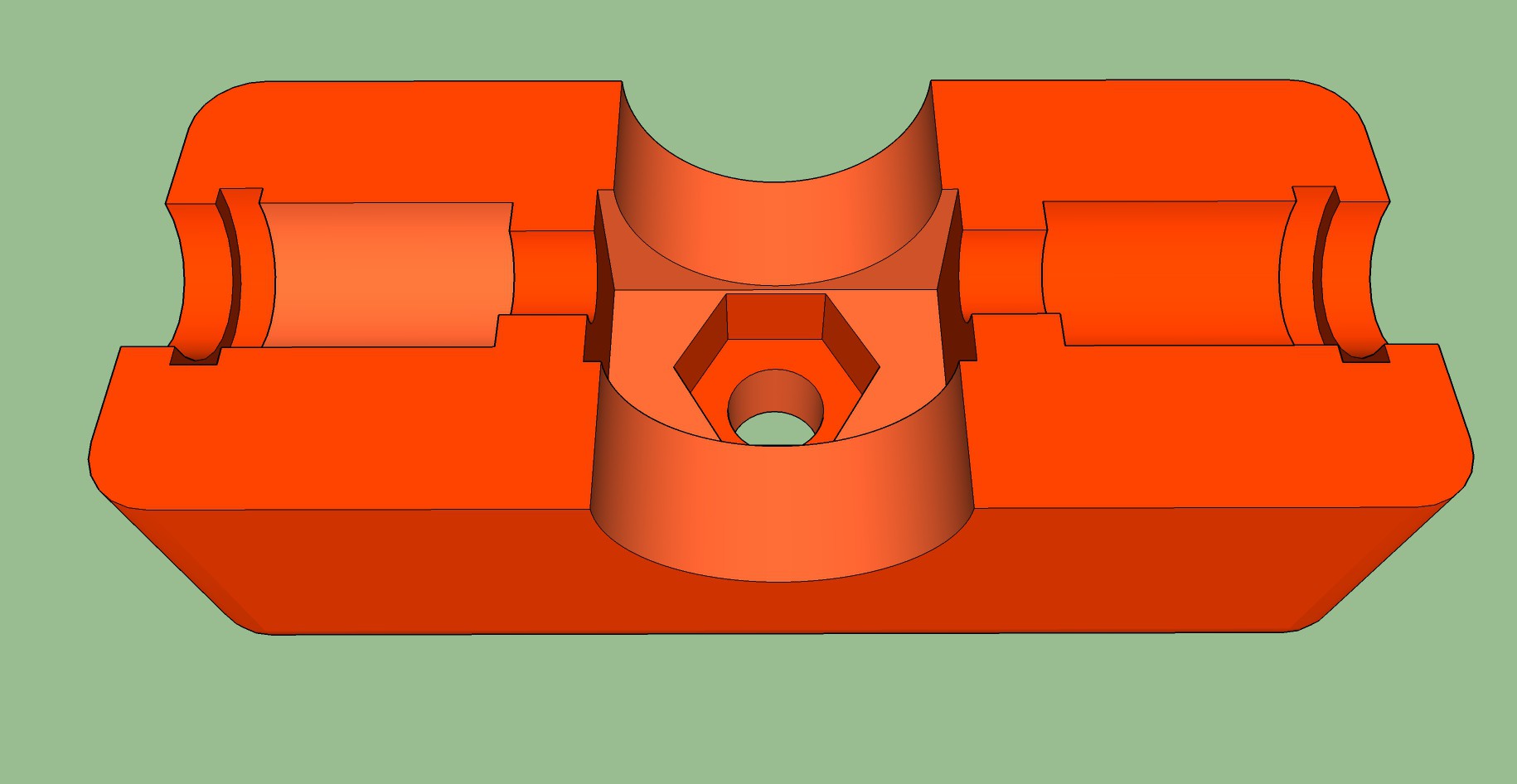
The central hole allows the whole shell to pivot to allow for tube movement, or different sized radii of the overall design.
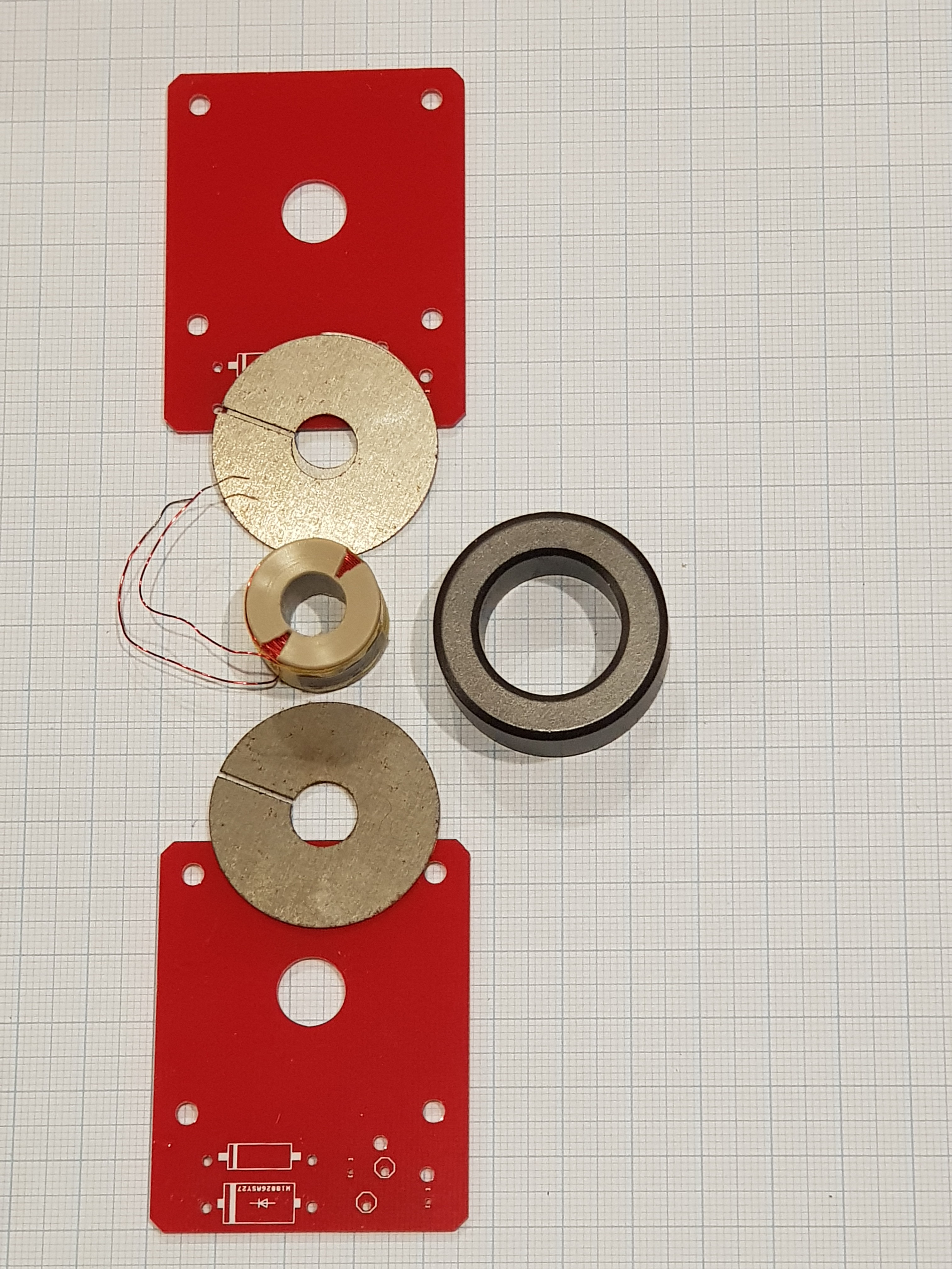
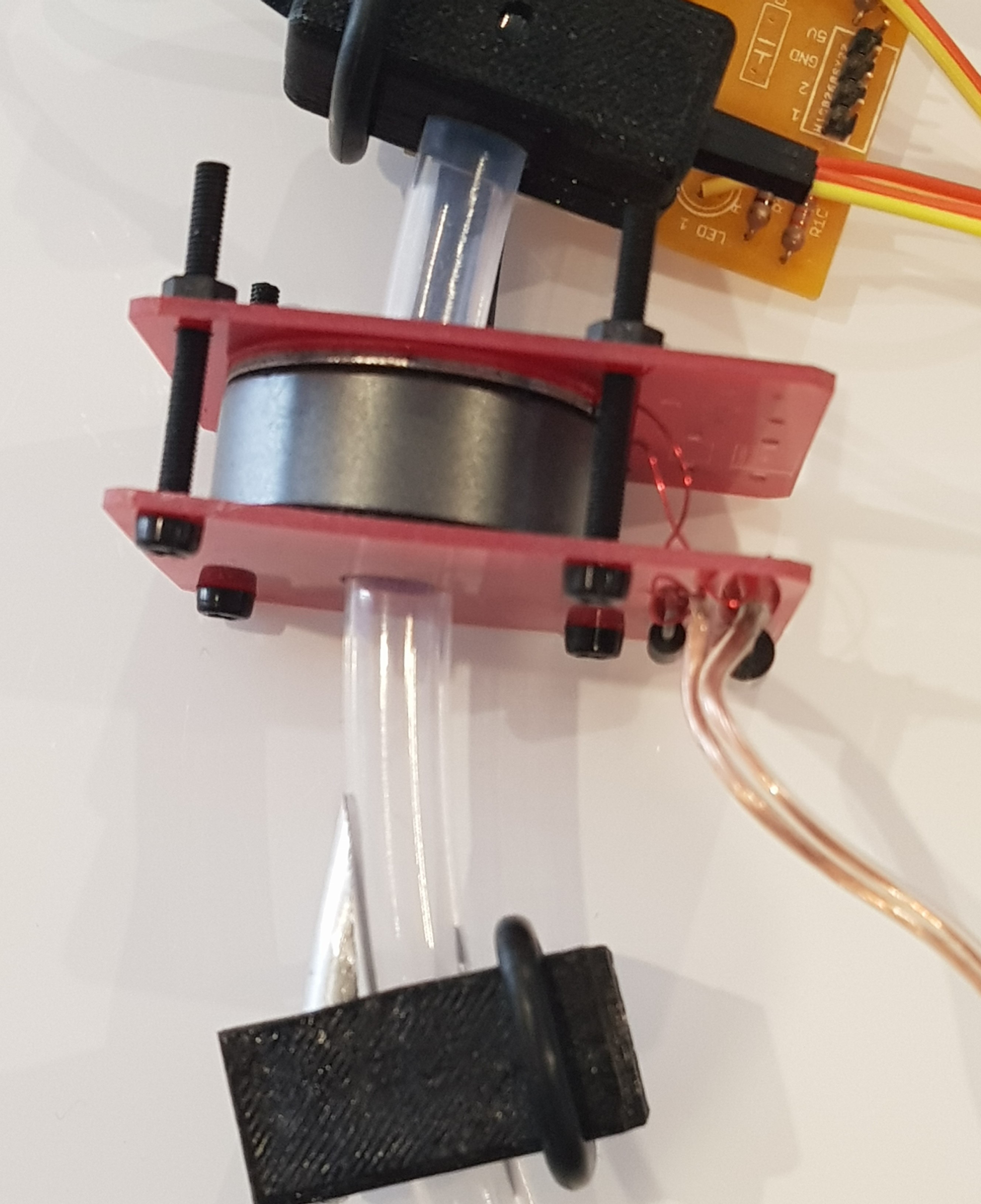
The design of the electromagnet system is critical to performance, with particular attention being paid to reducing the gaps in the magnetic flux path (eg. Air, plastic etc). The FEP tube chosen was as thin as practical. While winding the coil directly over the FEP tube would minimise the flux path, it was awkward to achieve as repositioning coils along the tube became difficult, so it was reluctantly decided to use thin wall bobbins. A range of existing commercially available bobbins/solenoid coils designs were reviewed for compatibility with tube size, however no suitable match was found and a custom designed bobbin was required. Rather than 3d print bobbins, which would requires several mm wall thickness, a custom bobbin was CNC machined with approximately 1mm wall thickness. Overall, the electromagnet system consists of bobbin with winding, ferrite toroid, steel laminations, the PCB's used to hold the components together, and the steel ball. Using a ferrite ball was considered to avoid the braking currents flowing due to Lenz's Law, however, cost-effective ferrite balls could not be procured. Home made ferrite balls were attempted, however, they proved to be difficult to create with sufficient surface smoothness to allow consistent rolling.
The disassembled electromagnet
The photo below shows the electromagnet assembly between two red PCB's.
The Output board includes a dedicated logic level MOSFET for each of up to six electromagnets, and interfacing electronics from the Arduino. The electronics decode the 3 wire output address bus from the Arduino. A LED bar graph shows which electromagnet is operating, and the sequential progression of the bar graph pulse assists in ensuring correct configuration and operation. A parallel circuit triggered from the output address bus connects to strobe LEDs to indicate when each electromagnet is energized. The LEDs are housed in aluminium light pipes, cut at an angle...
Read more »


 Stuart MacKenzie
 Tamas Feher
 Facundo Noya
That is a really impressive project, and very inspiring.