Close
0%
0%

FR-4 Lightpipe Experiment #1

Oreo construction PCB lightpipe for cool badge art

Similar projects worth following
Conbadges and user interfaces occasionally use FR-4 as a light diffuser with downward facing LEDs or a secondary PCB. In this experiment I will attempt to install LEDs internally within a single PCB and release diffused light through surface features.

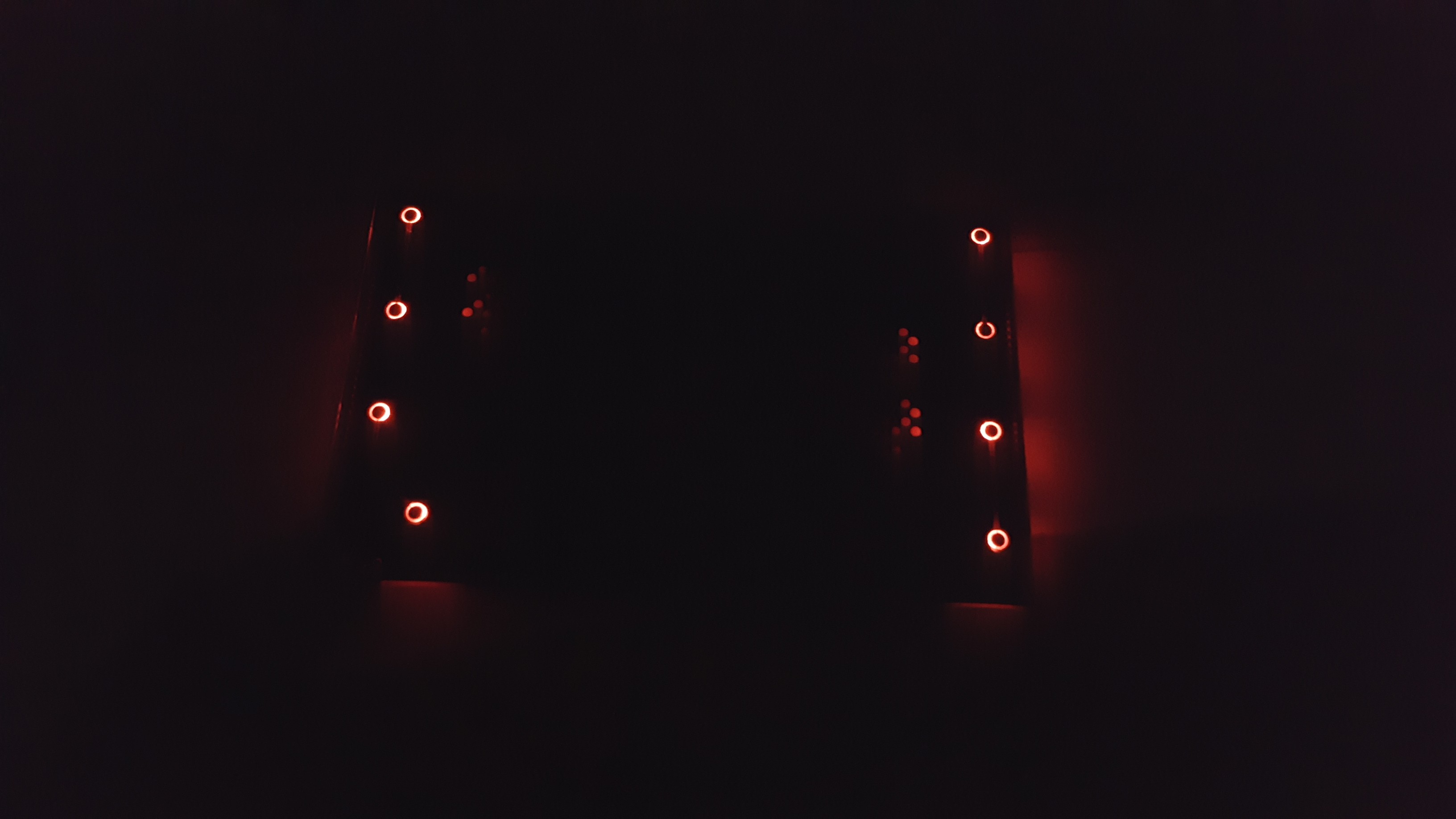
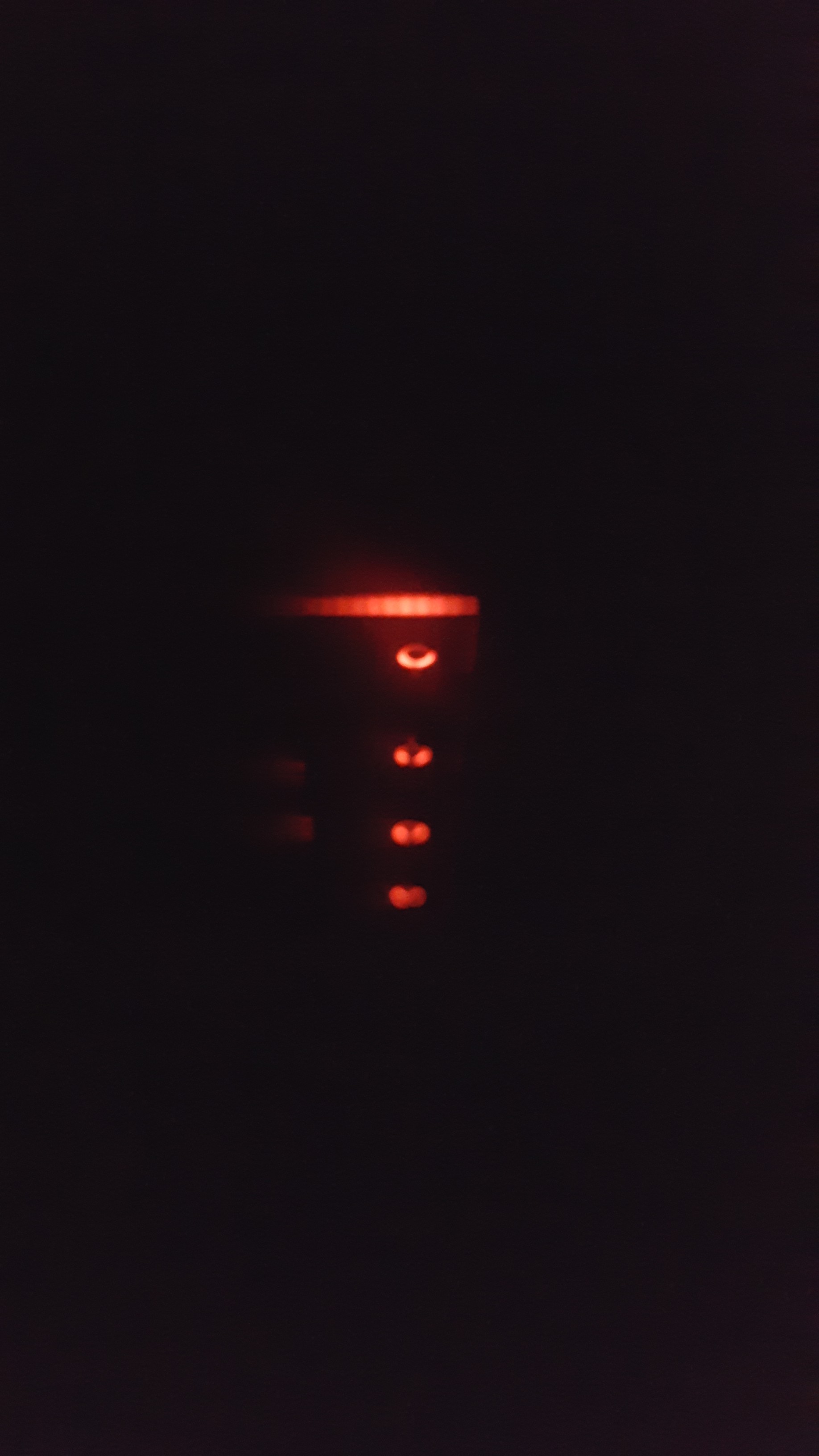
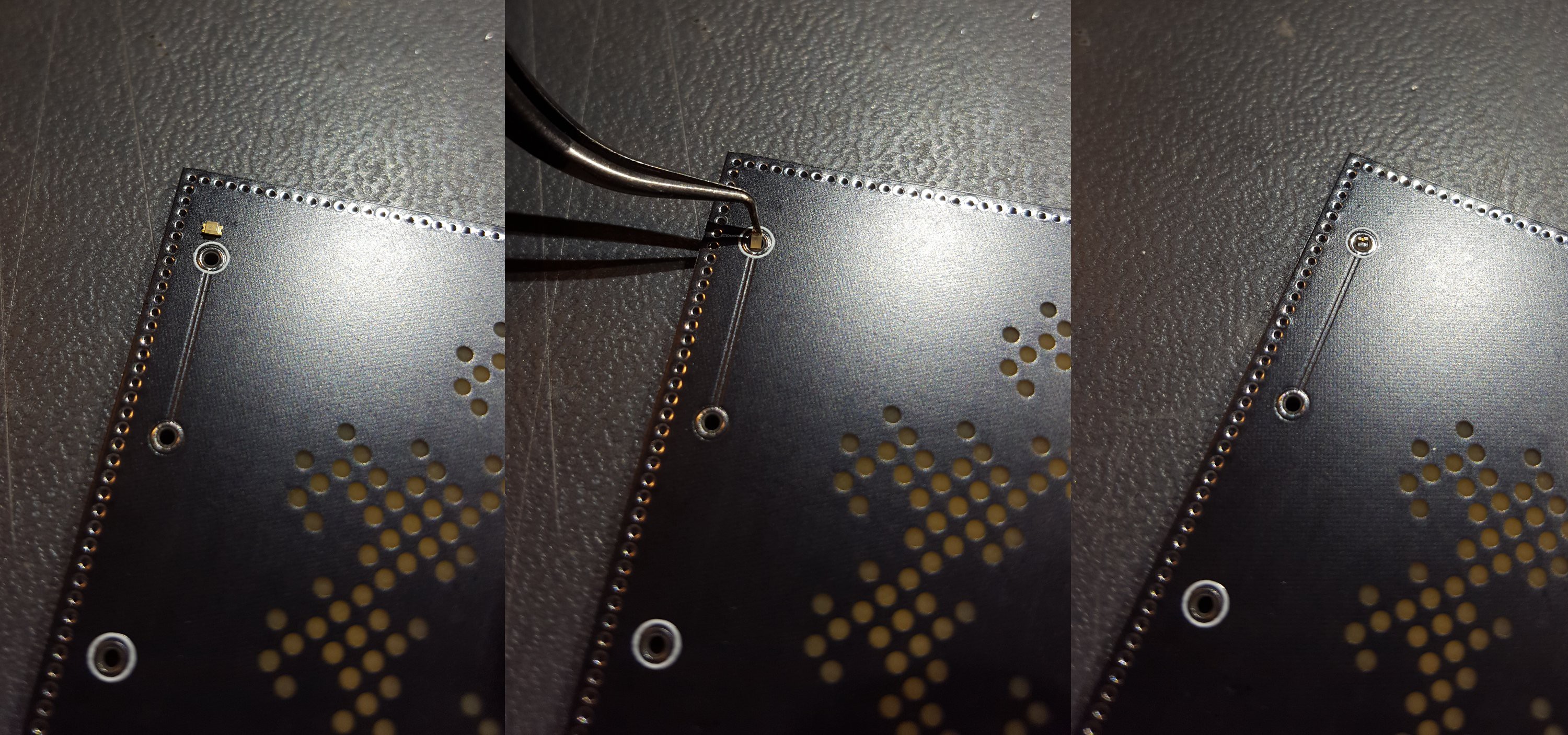
The basic concept is to insert LEDs vertically through non-plated holes. Solder will connect the component leads to exposed copper annulars on the front and back side of the board and retain the component inside the hole. 0603 parts are just slightly shorter than a standard 1.6mm PCB and a 0.8mm tall LED fits snugly into a 1.1mm hole. LEDs are positioned facing inward.

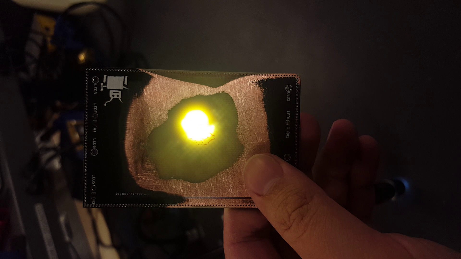
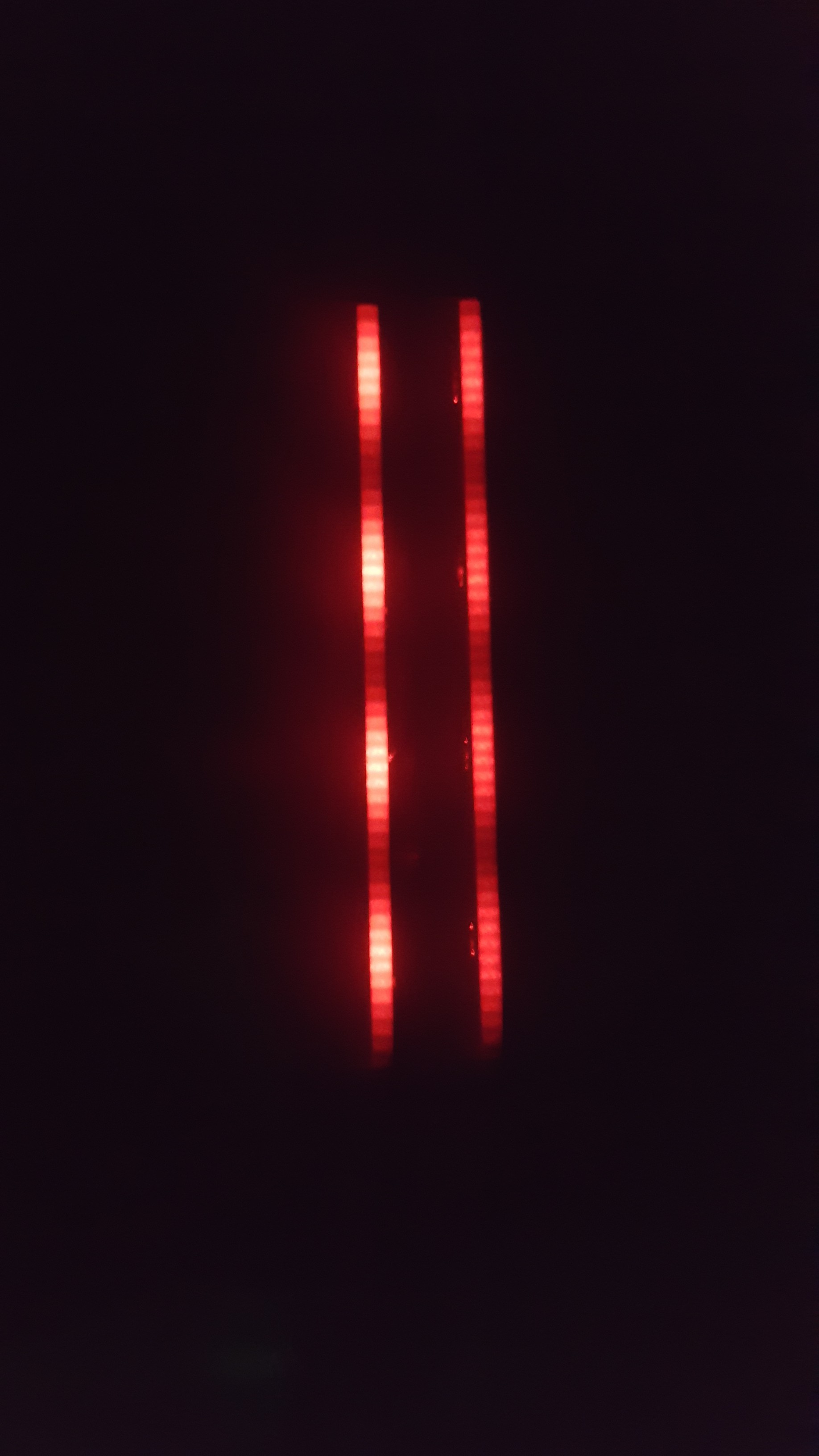
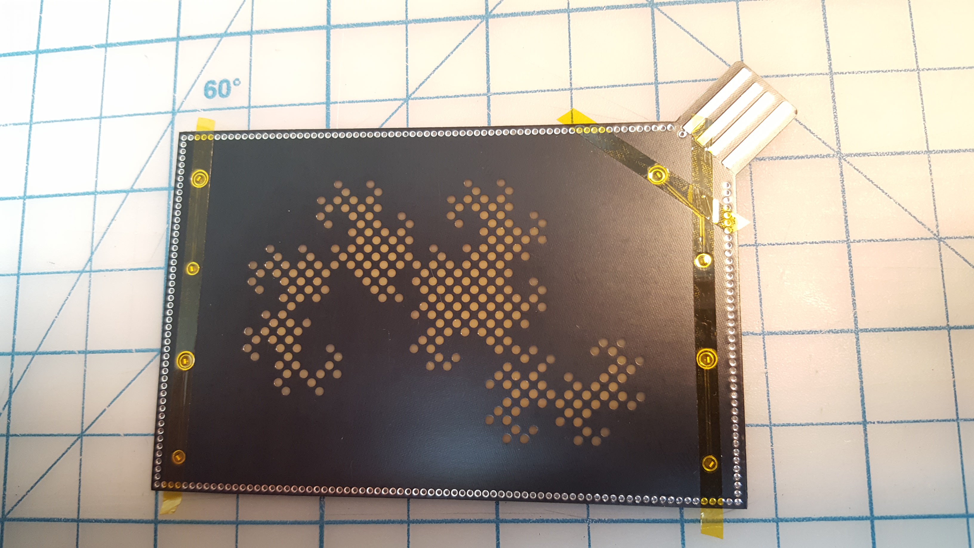
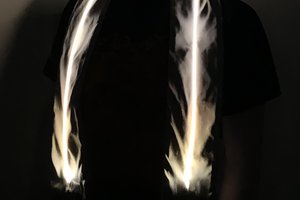
Light is confined within the FR-4 substrate with copper pours and a via fence around the outer edge of the board. The reflective underside of the copper will redirect light toward the center of the PCB. Holes in the front copper pour and soldermask allow light to exit the board.

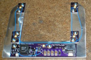
Power is supplied to the board using a PCB USB-A plug. Two layers of electrical tape are applied to the underside of the plug to bring the 1.6mm PCB to a standard USB plug thickness of 2.2mm.

  • Conclusion

    Jeremy Ruhland08/13/2019 at 05:44 1 comment

    This rev of the board did not perform as expected. Although the via wall appeared to successfully redirect the majority of the light into the FR-4, illumination only occurred within 15mm of the LEDs.

    Edge view

    As a test I pressed a powerful external light to the front surface of the board but was unable to see any light emerging through the empty NPTHs. I also removed a portion of the bottom copper pour using sandpaper to observe the translucency (mp4).

    In another test I installed the LEDs facing outwards to judge how effective the via fence was.

    Left, LEDs facing ourward. Right, LEDs facing inward.

    FR-4 apparently absorbs a lot more light that I thought. It doesn't seem like all that much when an LED only has to go through 1.6mm of it but in my tests 15mm was the limit of transmission with the aid of the copper pours. I estimate each LED was putting out a third of a lumen, so the entire board had about 2.6.

    Fiberglass is an anisotropic material but I'm not sure how its optical properties change with orientation to the weave. Would light travel any better front-to-back through a PCB 10x as thick? It seems like the glass fiber would absorb less light than the epoxy since glass is kinda known for its transparency but there's a lot more scattering surfaces parallel to the fibers so light transmission might be worse in this orientation. Transmissive properties may differ with wavelength as well.

    In a future rev I would like to try cramming an unreasonable amount of LEDs into the board but I think this method of illumination is a dead end. The ultimate limit is the thermal dissipation possible with 0603 LEDs that are buried inside FR-4. Larger (and brighter) packages will not fit within the 1.6mm PCB.

    The oreo construction method might prove useful for other projects and should be explored further.

  • Assembly

    Jeremy Ruhland08/13/2019 at 05:27 0 comments

    Assembly of the board was straightforward. LEDs fit easily into their holes as long as they were aligned normal to the surface. Friction was sufficient to hold them in place before soldering, even if the board was lifted.

    Care had to be taken while soldering to ensure the solder successfully made contact with the component leads and did not simply dome over it. Diagnosis can be performed with a multimeter in diode mode. Connection to ground pours was difficult despite thermals but it worked well once the copper heated a bit. I cannot recommend using additional flux for these components as the off-gassing causes the cavity to pressurize while the final solder cap is cooling and it will pop like a bubble.

    Installation of the oreo LEDs. This was a test fit, the final position had the LED rotated a little to point more directly toward the center of the board.
    This tape turned out to be unnecessary, the LEDs are held in just fine by friction.

  • Fabrication

    Jeremy Ruhland08/13/2019 at 05:05 1 comment

    I went with JLCPCB to fabricate these boards and was very happy with the quality. I emailed them beforehand to ask about how they wanted me to notate NPTHs that went through copper pours (usually this signals a PTH). In the end I added a build note to my documentation gerber which called out the drill diagram and I exported two different excellon files, one for NPTH and another for PTH. I also noted this as a comment on the online order form.

    They also honored my request to place order number codes on the back side of the board to keep the front pretty. Due to process limitations they weren't able to drill directly through the copper like I wanted but they added a very small pullback to the annular and drilled through the exposed FR-4 which didn't present any problem for assembly. In the future it would probably be easier to modify my library component to present this part as a standard NPTH surrounded (but not touched by) a ring of exposed copper to preclude the need for all these notes.

View all 3 project logs

Enjoy this project?

Share

Discussions

chris wrote 08/20/2019 at 23:08 point

Ignore my comment, I didn't see the link to the design files on the left. 

  Are you sure? yes | no

chris wrote 08/20/2019 at 17:53 point

What size holes did you use? I'm contemplating doing something similar for a motorcycle speedometer. I want to do reverse mount LEDs for the indicators.

  Are you sure? yes | no

Pierre-Loup M. wrote 08/20/2019 at 08:07 point

Would it be possible that instead of a single board, you pile three of them ? Two thin layers on top and bottom, containing the led traces as you did, and one thicker layer in the middle, serving as a spacer. And to have an inside shape where the FR4 is removed, so the light travels freely. This way you could use a few millimeters of FR4 near your led for diffusing. I can't figure how the light would behave exactly, and if it would shine well through the surface, as it's perpendicular to its original direction. Maybe bare copper on the upper layer of the bottom side would help ?

  Are you sure? yes | no

Dan Maloney wrote 08/15/2019 at 20:38 point

So what if instead of non-plated through holes you did long slots like the kinds used for HV isolation? Those could hold perhaps a dozen or more LEDs in a similar fashion, and really push up the light level.

  Are you sure? yes | no

Ian Shannon Weber wrote 08/13/2019 at 22:56 point

Were you using any models for the diffusion? I have been thinking of making something with diffused LEDs through FR4, but I have been scared of spending money on the experiments.

  Are you sure? yes | no

Similar Projects

Does this project spark your interest?

Become a member to follow this project and never miss any updates