Close
0%
0%

How to test transistors

3 methods for testing BJT

Similar projects worth following
1.3k views
How to test Bipolar Junction Transistors?

I know a lot of you are pass this point in their career but I will just post this up here because I realize there are so many young persons out there searching for this bits of info. 

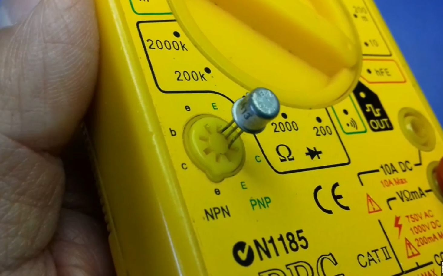
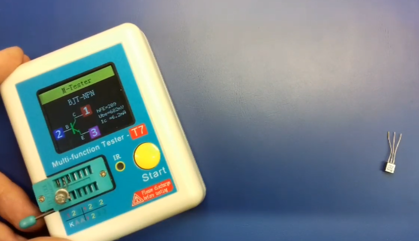
A little theory didn't hurt anybody so... These 3 methods are the ones I use the most in my daily job and they never failed me. That's why I said to myself that I need to compile them in a short instructive video everybody could understand without too much math and chemistry. I will also list them under the Instructions section just to leave room for extra discussion and to be able to post some other written explanations related to the topic.   

  • 1
    The first method

    The first method I’m using the most, is the LED method. So suppose you don’t have a multimeter around, simply garb a 5 to 12V voltage source. It can even be a 9V battery or something similar. 

    • Connect the + to the collector,
    • Connect the anode of the LED into the emitter
    • And the - in the cathode of the LED like in the picture below.

    This setup is very quick and you don’t need to solder anything. Just use an alligator clip  or something similar like I’m using in this example.

    Then open the junction of the transistor by touching with your finger between collector and base like this. It helps if your fingers are not very dry.

    Or by simply touching the base. Your body usually behaves like an antenna and will pick up some alternating millivolts from the environment. Chances are that your body potential is significantly different then the source voltage of the power supply and you only need about 0.6V to open the Base-Emitter junction through the resistance of your skin.

    To bias a PNP transistor in this mode you would have to touch the base and the ground in the same time like this:

    I used this method successfully without burning any transistor so far. I guess the explanation is that the skin resistance is very high. Something between 200Kohm and 10Mohm. This only allows a very small base-emitter current and the transistor will never saturate. 

       I realize this method has it's downsides and it could expose the component to a small chance of possible ESD damages. Accidentally touching the + to the base of a NPN transistor could definitely fry it and the LED.  On the other hand it is very graphical and good for demonstrative purposes, especially for beginners and students. 


  • 2
    The second method

    The second method is using the diode function of a multimeter.

    You will have to set the multimeter to this diode function.

    For testing the NPN transistor, place the positive (red) lead on the base. Test both of the junctions as you would test two diodes in the same package that are having the base as the common lead.

    For the PNP Bipolar transistor you must place the negative test lead on the base. Then test the inner junctions as you would test diodes. Depending on the type of the transistor and the size, you might get junction dropout voltages between 0.4 and 0.7V.

    This test tells you if the internal structure of the semiconductor is being damaged or not. Testing the transistor this way will reveal short circuited or broken junctions. If everything measures within the limits, it means the transistor is OK and will most likely behave normally any circuit.

    I have seen some other weird cases with array type junction transistors that were only partially breached and were creating noise in PA systems. There are some other cases of partially damaged transistors due to the semiconductor diffusion effect which could pass undetected when testing them using these first two methods. But this is maybe making the subject of another article.  

  • 3
    The third method

    The third method for testing transistors is to use a multimeter that has a transistor testing function. Insert the transistor into the special designated socket minding the terminals and the type. If the hFE (β) parameter shows up on the screen and it resembles the one from the datasheet, the transistor is OK. 

                    Or to use one of these component testers. The RLC component tester or M-tester T4 - T7. This is probably the fastest and most elegant solution for testing transistors as it will also give you the internal parameters and the pinout.

View all 3 instructions

Enjoy this project?

Share

Discussions

Similar Projects

Does this project spark your interest?

Become a member to follow this project and never miss any updates