 Mark Wilson
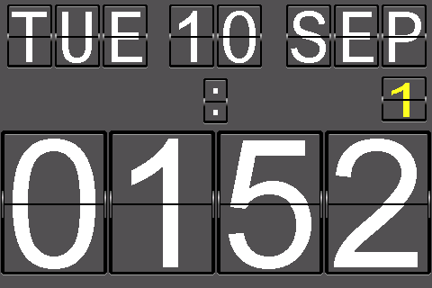
The main clock display is the day, date and month in smallish flip-style digits across the top of the LCD (landscape mode). The time is in big digits across the bottom. As a bonus, across the middle there’s a blinking/flipping colon and also a coloured digit indicating the number of days until I need to put out either the rubbish bin (red) or the recycling (yellow). It’s alternate weeks and I keep forgetting (this display is optional).
The time digits change with a detailed 3-step animation (top flap at 41°, 90° and 131°). The angles come from skipping every 4th row of the digit data, so it’s acos(3/4)=41°, close enough to 45°!
The LCD inspired me to add in some additional clock “faces”:
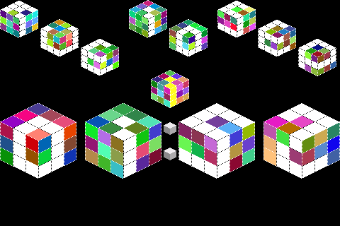
CubeClock
The LCD colours are appealing, so I experiment with coloured cubes. The look is based on this font www.dafont.com/kubics-rube.font
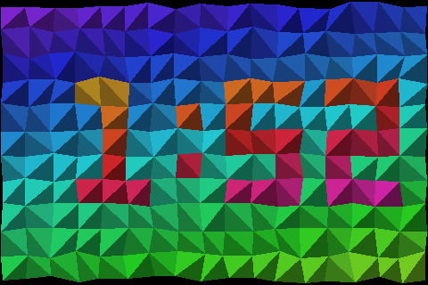
Triangle Clock
An adaptation of an eariler project with a triangulated irregular network (TIN) style face, more pretty colours.
PongClock
There was a little program memory left, so I squeezed in a very simple Pong Clock, again using code from an earlier project.
The sketch uses all but around 100 bytes of the Uno’s program storage space.
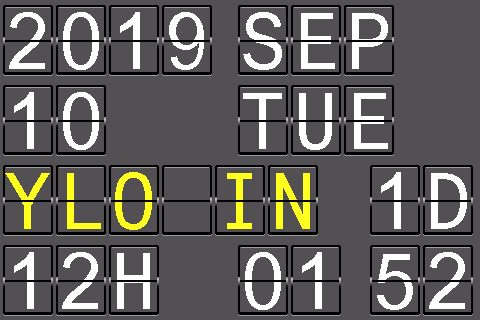
There are two push-buttons, Set and Adj. Pressing Adj from time display cycles through the faces (including a pseudo-face which randomly cycles through faces). Pressing Set from time display goes to the configuration screen. This uses the flip clock look. As well as setting the date and time it configures the red/yellow bin cycle (or none)
The clocks use a simple automatic DLS adjustment class which takes a table of start/end dates.
The LCD shield uses an ILI948x driver. As always, the trick is finding some code which successfully initialises the display (including orientation). The only other interaction is a) setting a “window” on the screen and b) filling it with colour data.
The viewing angle is fairly important, from the wrong angle the display is quite washed out.
This shield has a built-in SD-card reader, but no touch screen. Fortunately that leaves pins 10,11,12,13 and A5 free. I connected SET/ADJ push-buttons to 10 & A5 and used 11 & 12 as SDA/SCL for a software I2C to the DS3231 real time clock module.
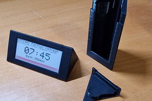
There was a lot of software in this project so when the time came to go from prototype to final assembly I decided to go to the other extreme and keep it as simple and minimalistic. It starts with a blank stackable shield. This gave me access to the pins I needed for the RTC and the two switches. I mounted all directly to it. The LCD shield goes on top, and Uno underneath to create a quite thick sandwich. This sandwich would actually have been enough, since it stands up OK. But I decided to add some protection in the form of two laser-cut clear acrylic plates. The Uno is attached to the back plate. The front plate is attached to the back plate with stacks of standoffs.
There is no backlight control and the thing is quite bright. To keep the build simple, there’s no LDR to sense ambient light and dim the display. Instead, there’s a bit of a hack in the sketch to optionally blank it between selected hard-coded hours (eg 7pm-7am). All that does is make the display black, but there’s still a glow - the copper tape is an attempt to reduce this light leakage. I plan a separate project with an LDR and a relay…
Video
Flickr album (pictures, with captions!)
Screen shots
Photographing the screen was tricky. I modified the sketch to optionally send the LCD commands and data out the serial port. I wrote a small Python program to read in a file of the serial output and re-create the image as a PNG.
 Arduino Enigma
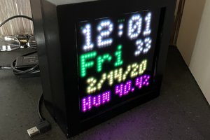
 Aaron Christophel
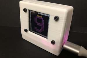
 kmatch98
Thanks Mark for you remarks, you saved me a standing amount of frustration. Never mind about gyros, they're for other project... And thanks for the heads up about DST. I owe you a beer! Now I'm waiting my hardware. For now I have a beautiful face is iddling 12:00.Let's how it comes with the DS 3231..Last subject, isit possible to change the black and white face for something like a deep blue and white? Your photo, and mine by the way, shows blue but it's black and white. Enough form today. Cheers, man!