 Jonathan Bumstead
MOTIVATION
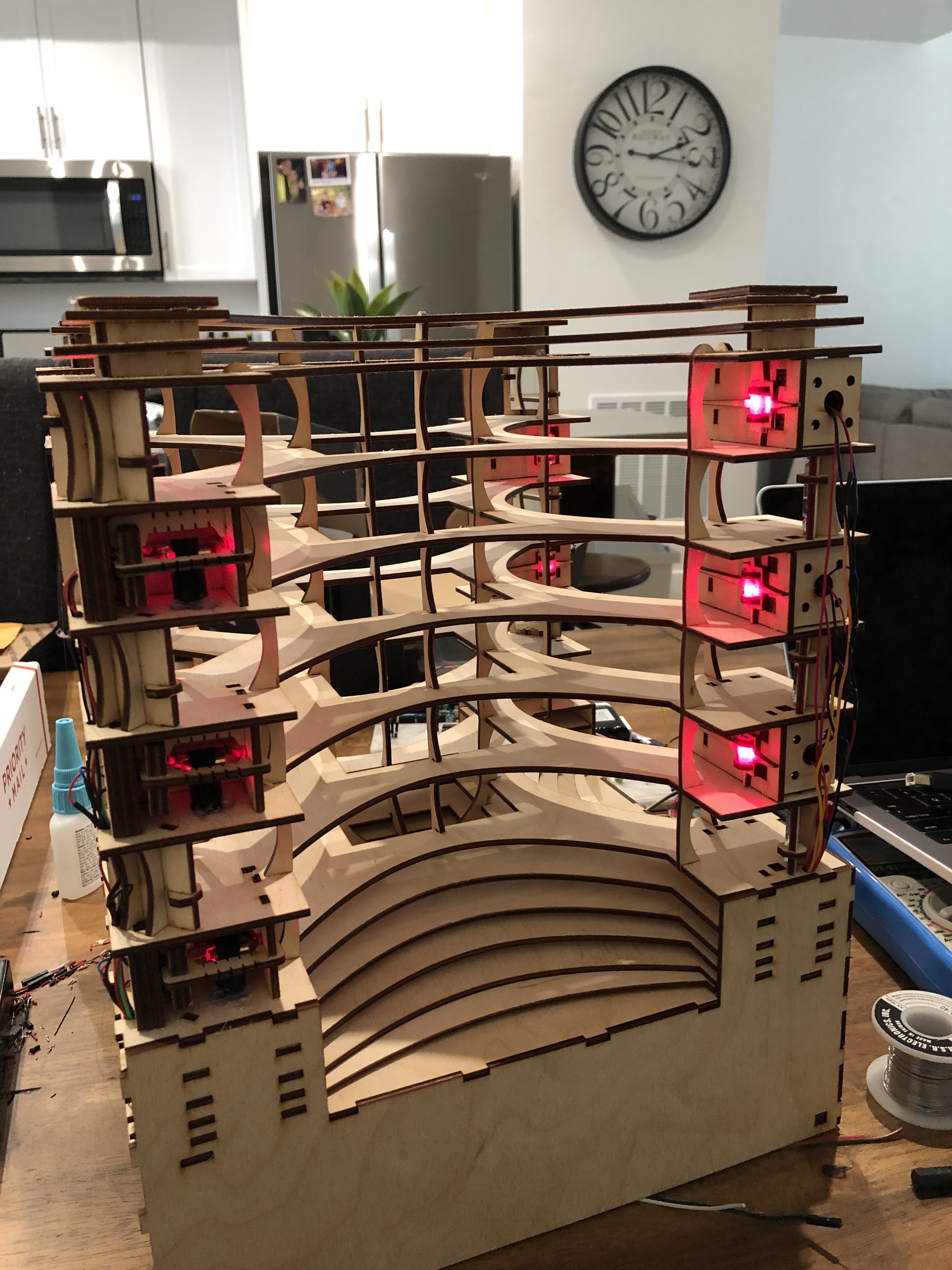
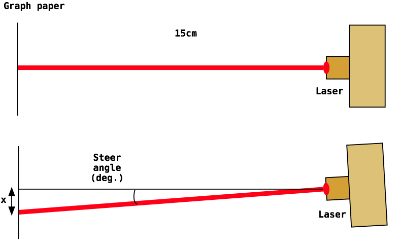
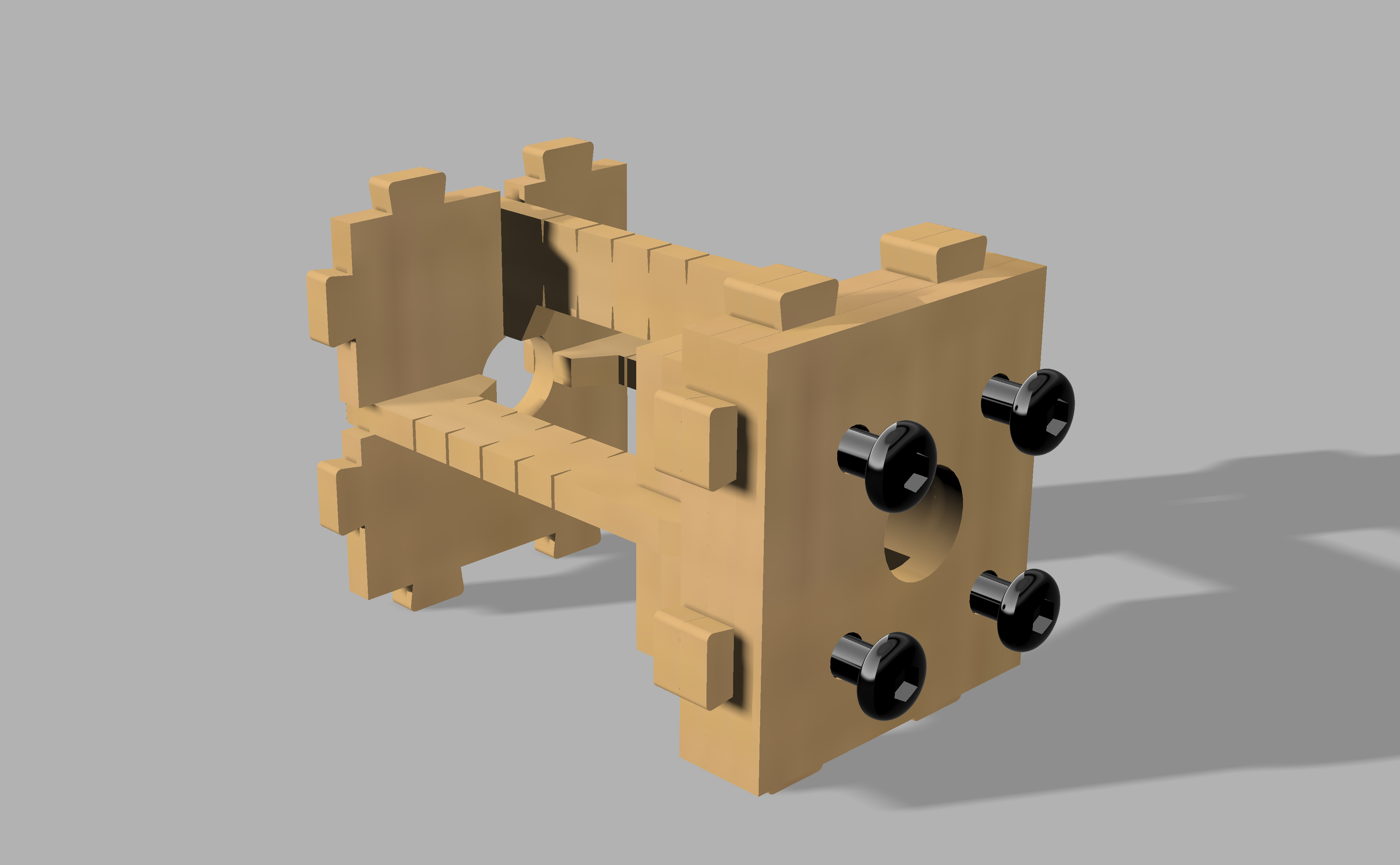
I was motivated to create a laser harp that was easier to play. With this design, the lasers land on "frets," which makes it much simpler to block notes with a single finger. Usually laser harps are played by blocking the beam with your entire hand, while this device plays more like a conventional stringed instrument. It is also a major challenge to align lasers with photodetectors, so my goal was to develop a mechanism that enabled fine-tuning of the laser beam direction without having to go through painful alignment.
There is so much to learn from building and programming the device, from laser beam alignment to controlling motors, Hall Effect sensors, and rotary encoders. That’s why I’m really excited to make it into a kit. The device is unique because it sits at the intersection of art and engineering, two disciplines that are often treated separately, and teaches how both approaches to thinking are important for design.
I hope the kit promotes interdiscliplinary learning and motivates musicians and engineers to learn coding, electronics, and how to play music. After completing the kit, the upright laser harp has lasting interactive potential.
SYSTEM OVERVIEW
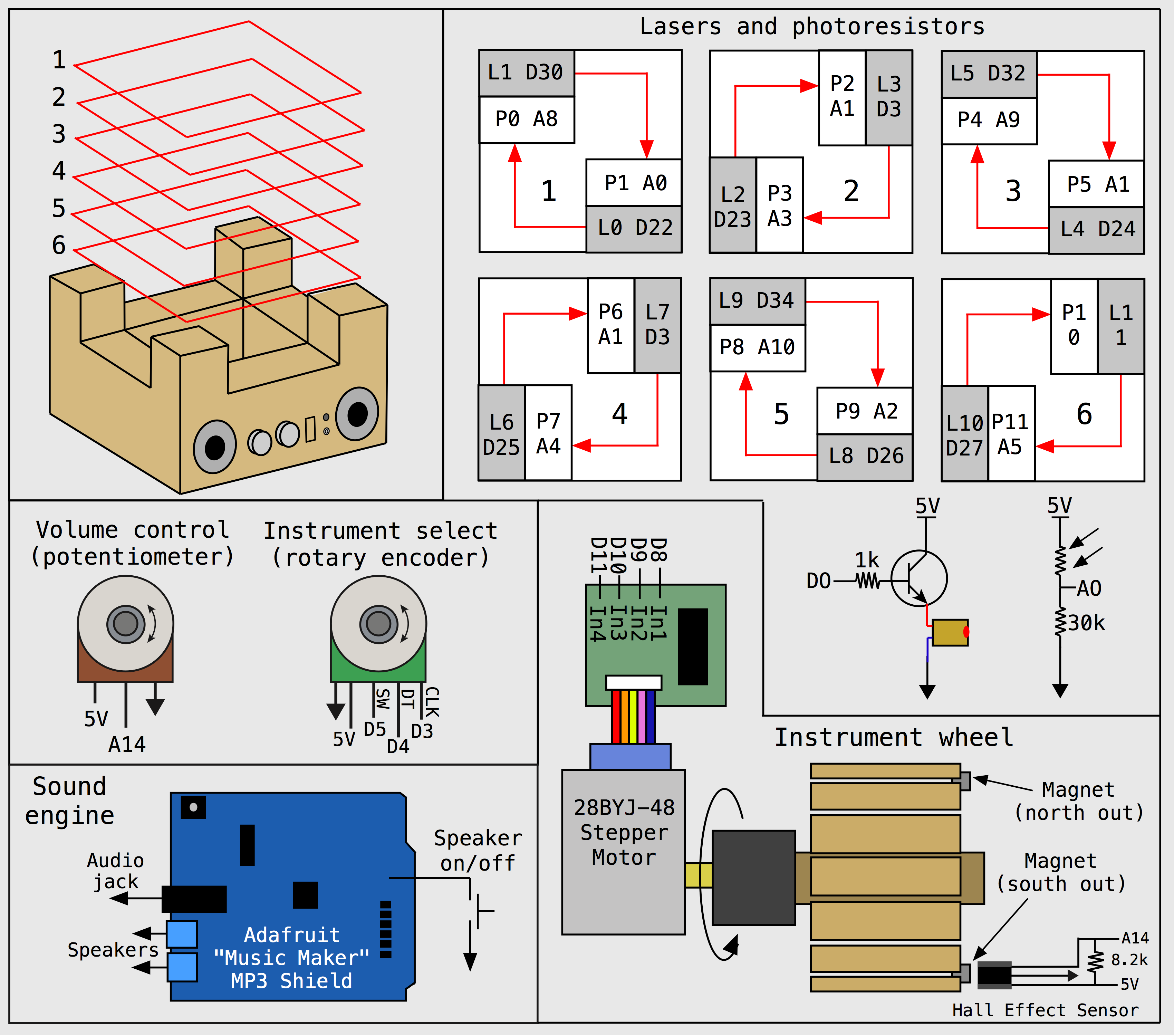
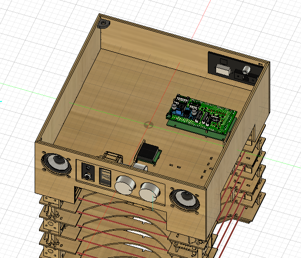
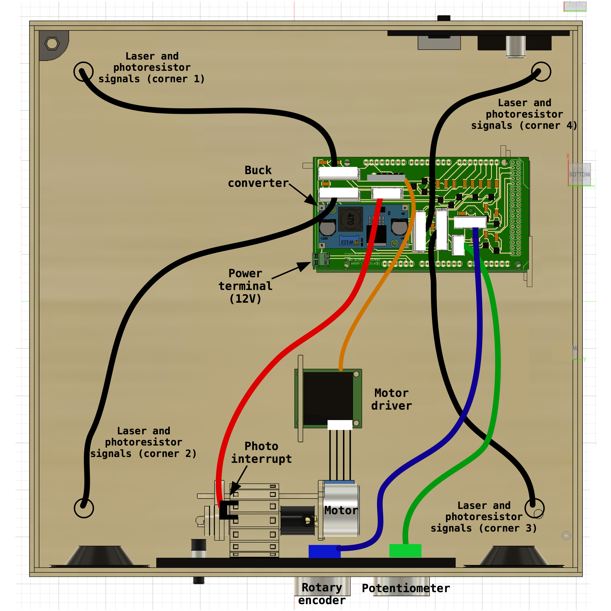
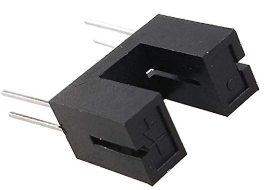
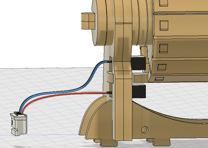
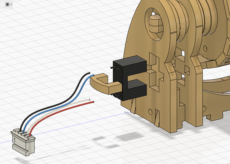
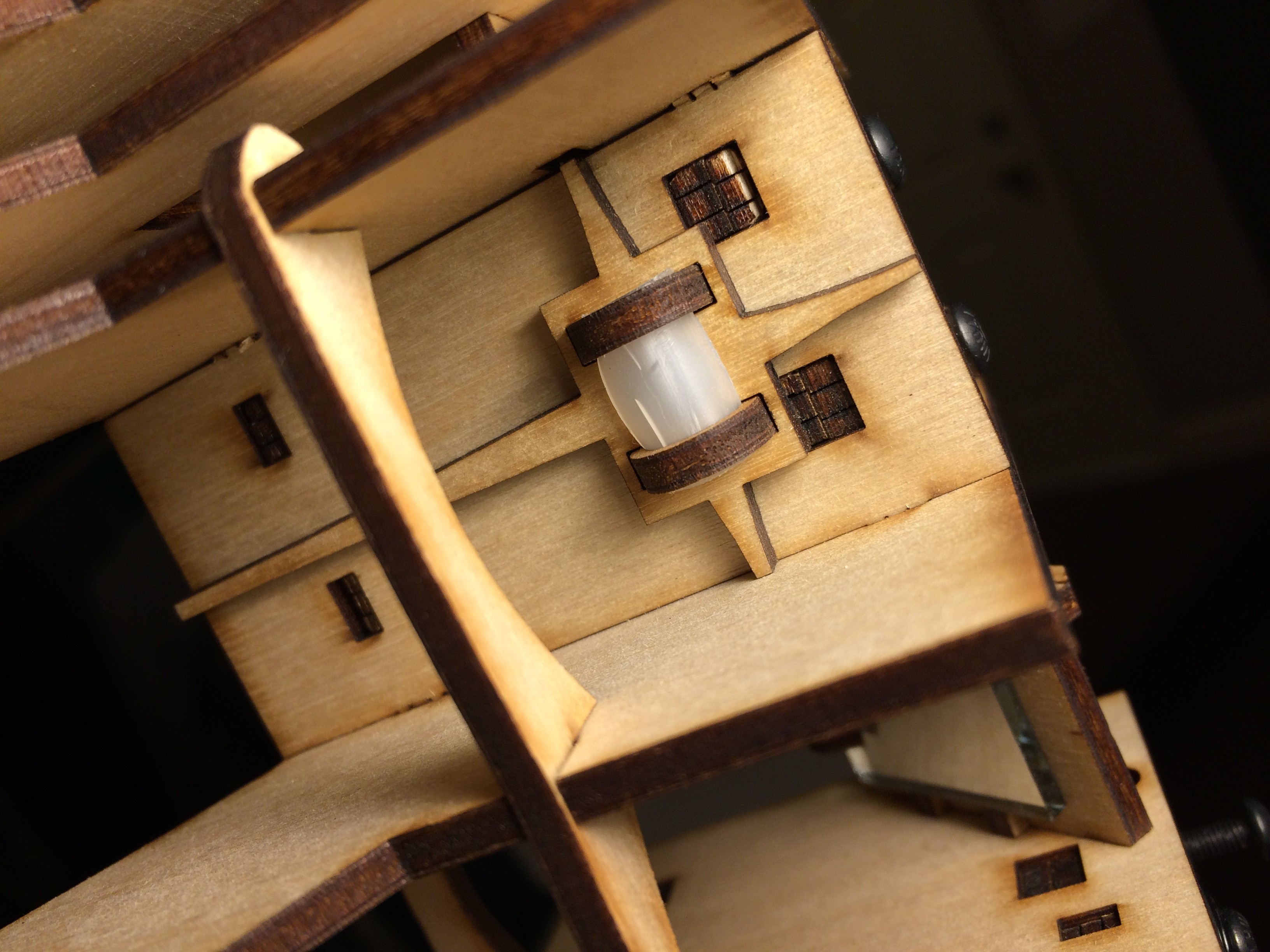
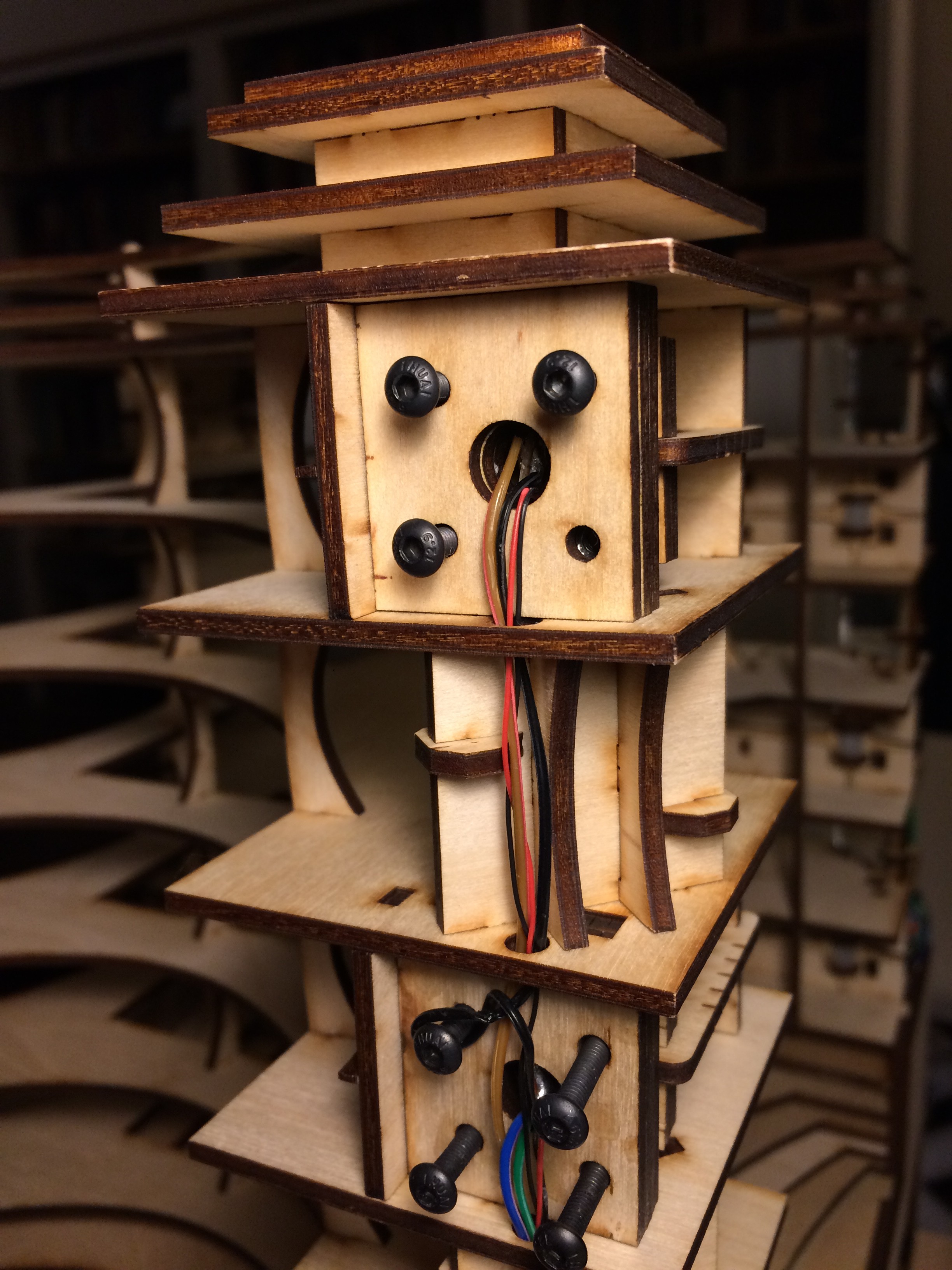
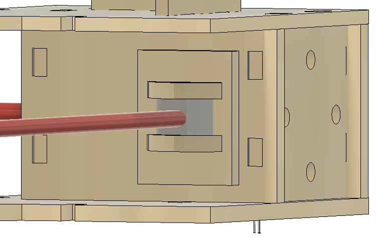
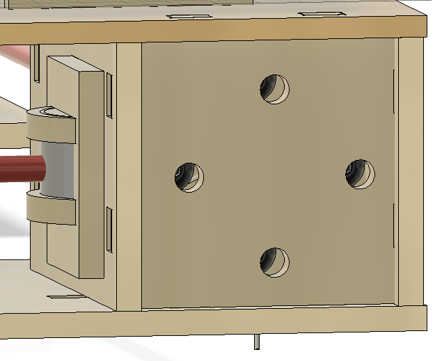
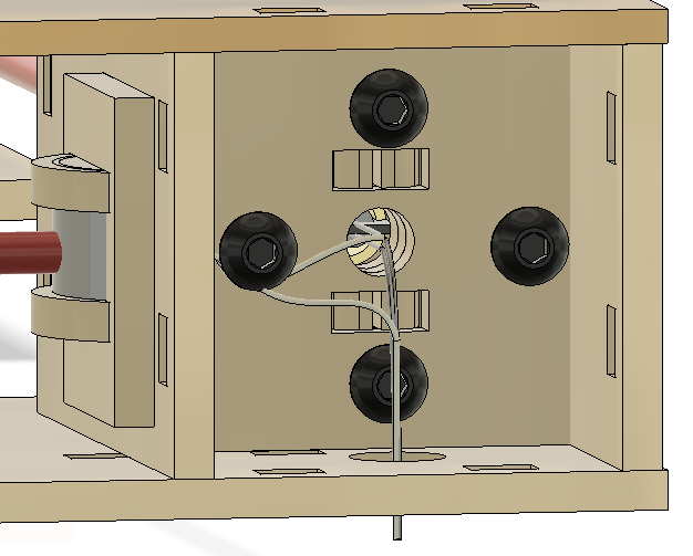
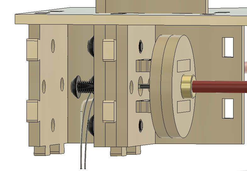
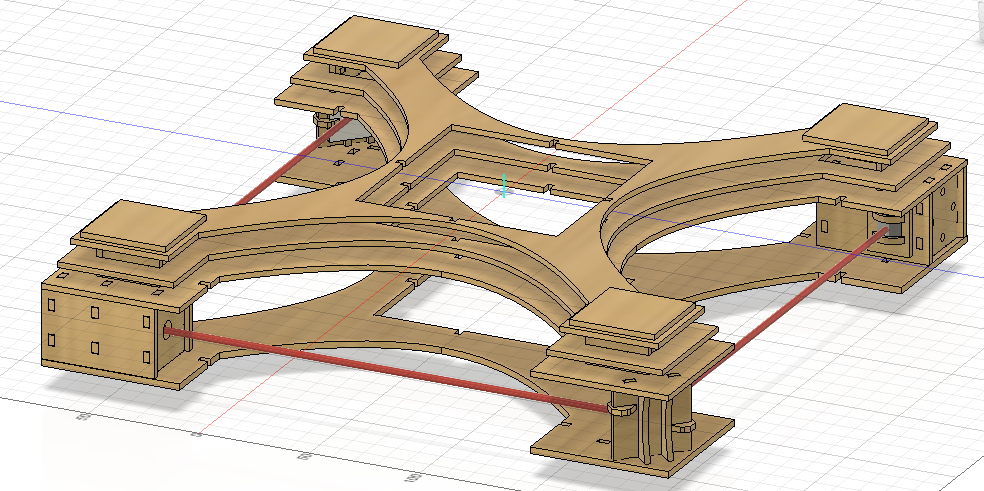
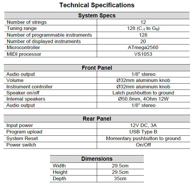
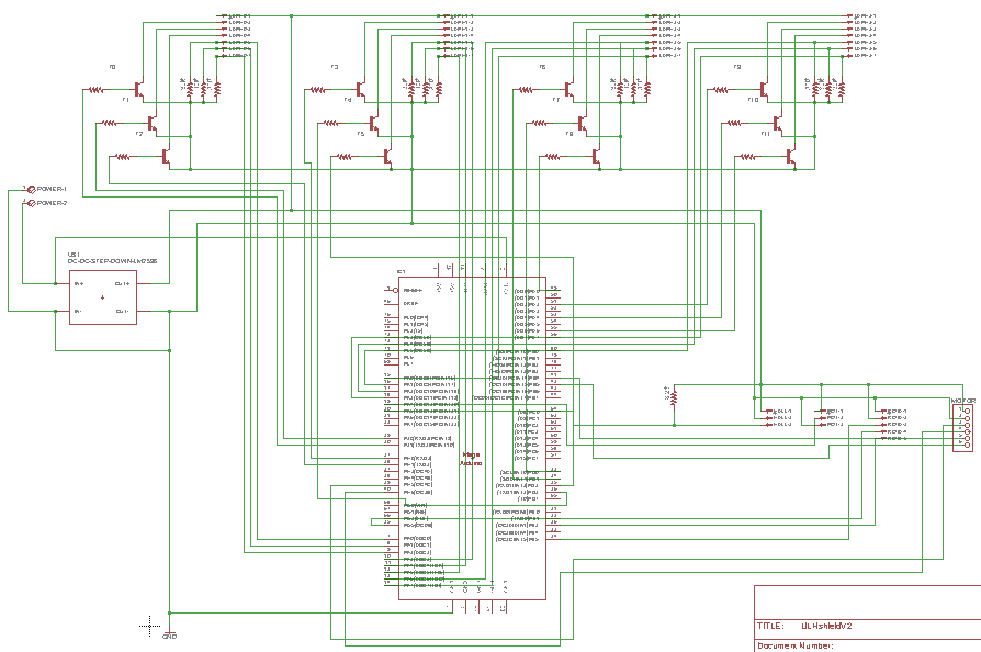
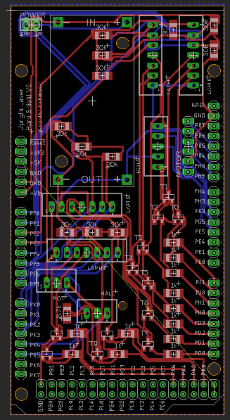
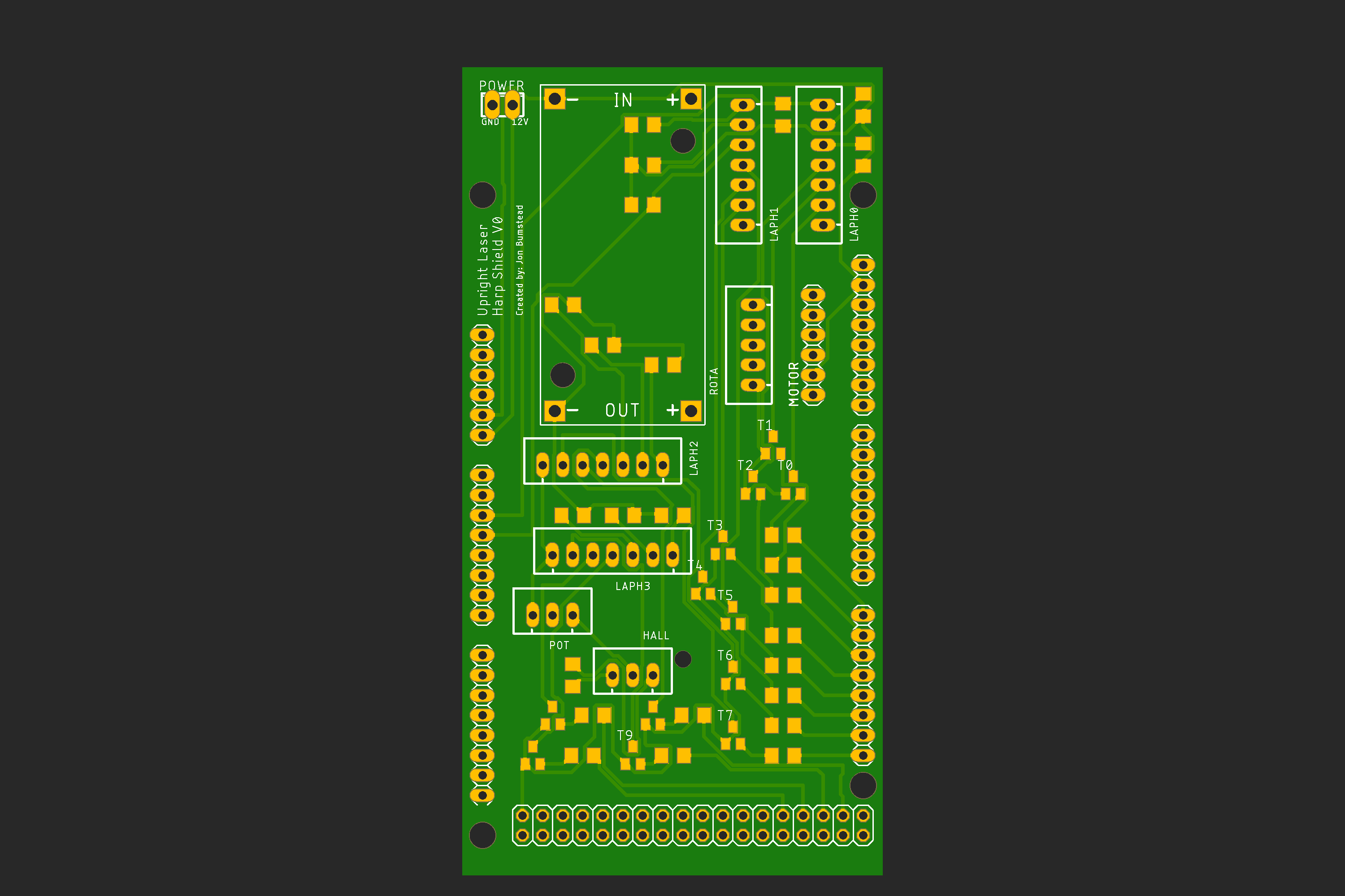
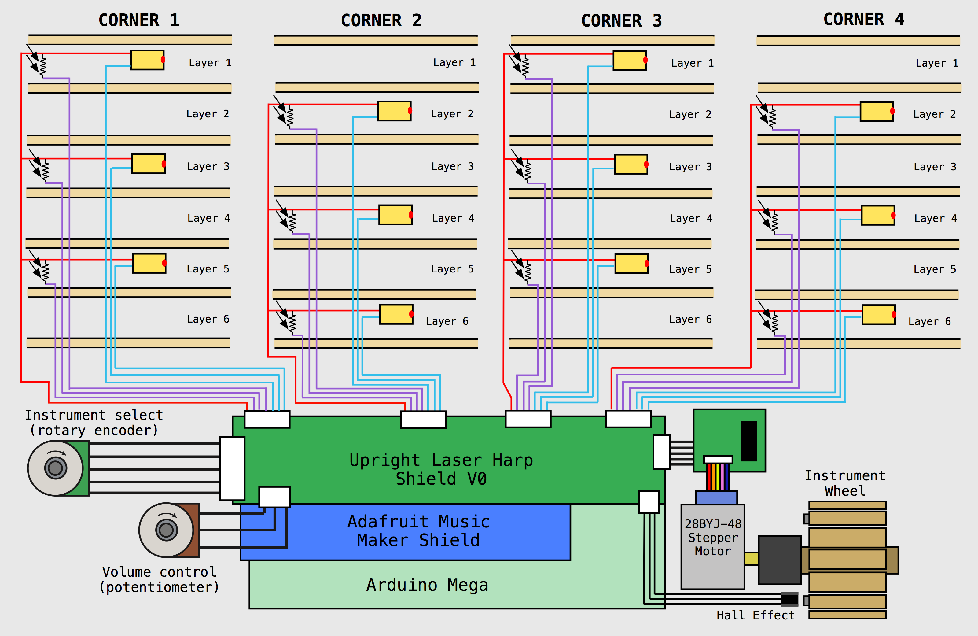
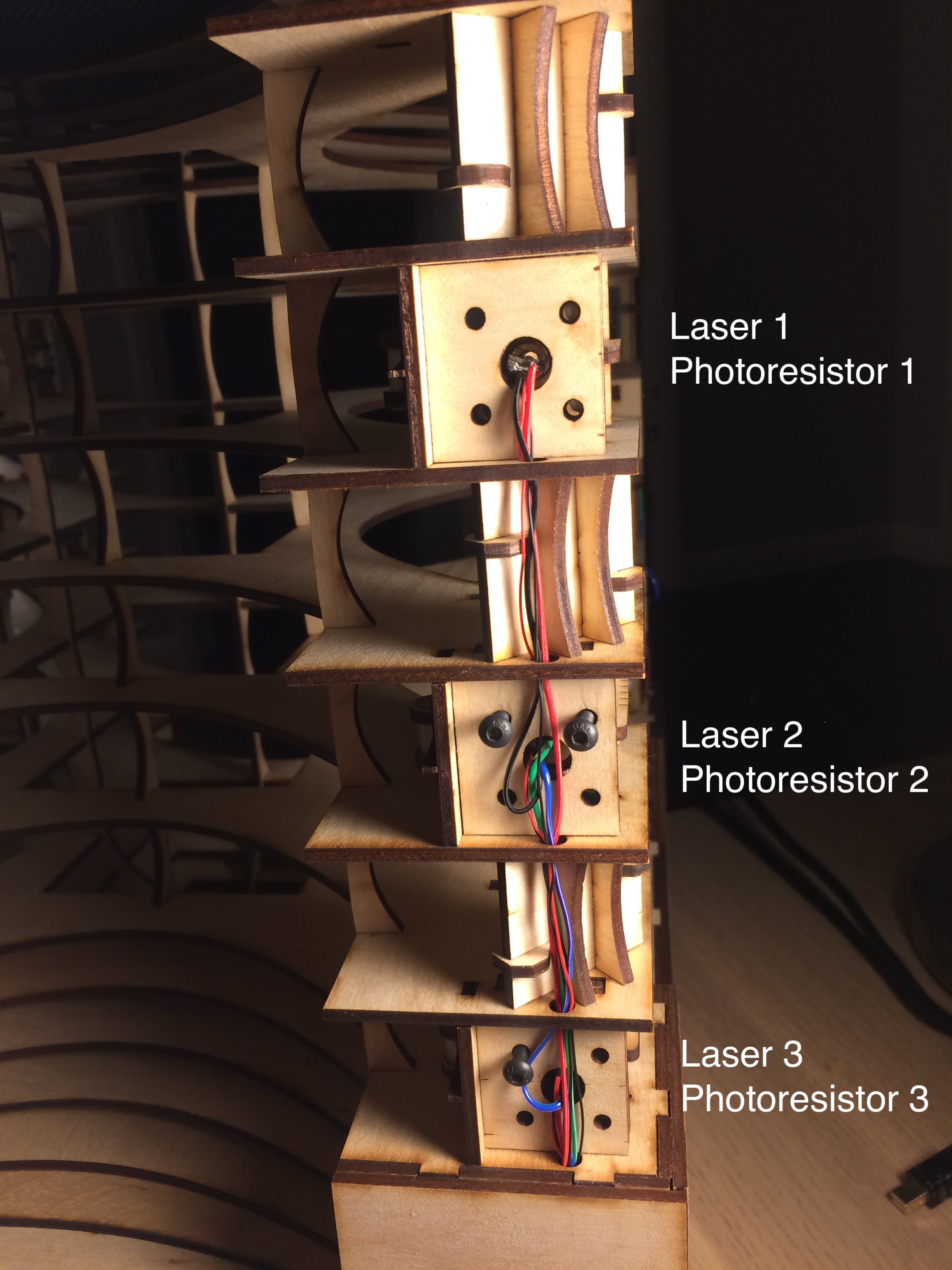
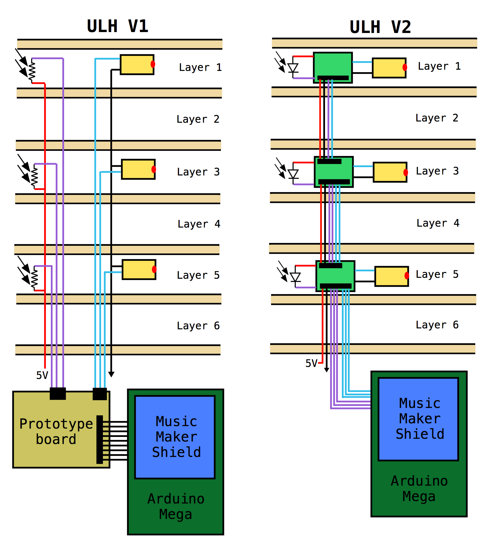
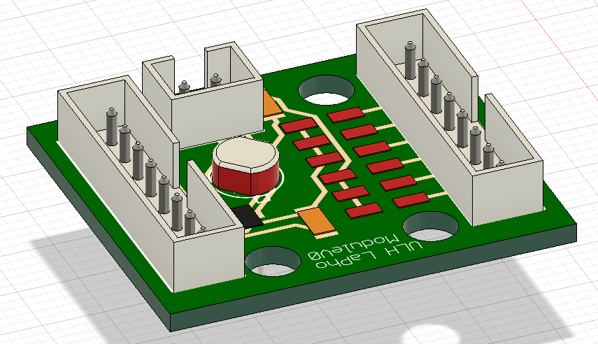
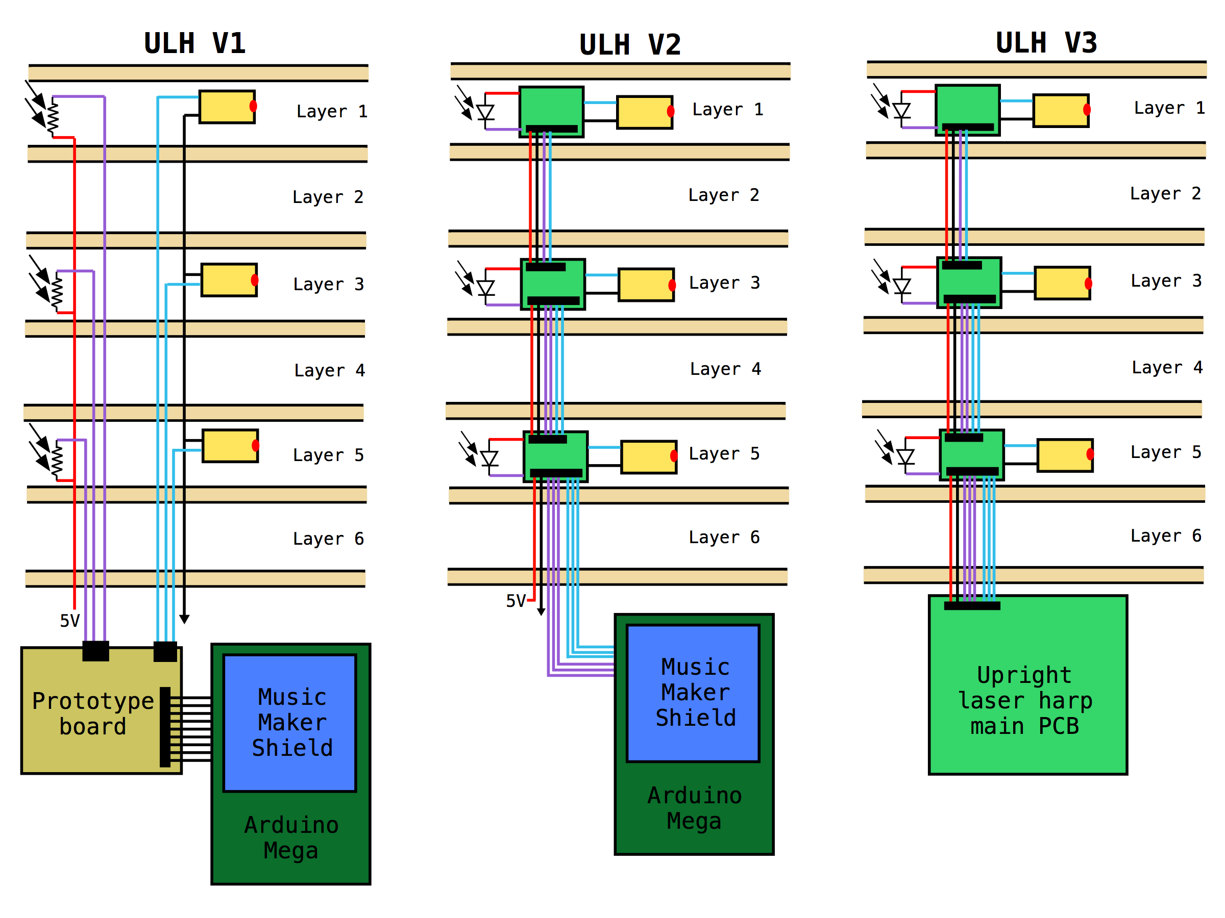
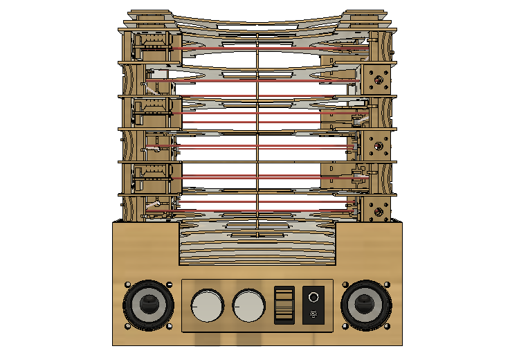
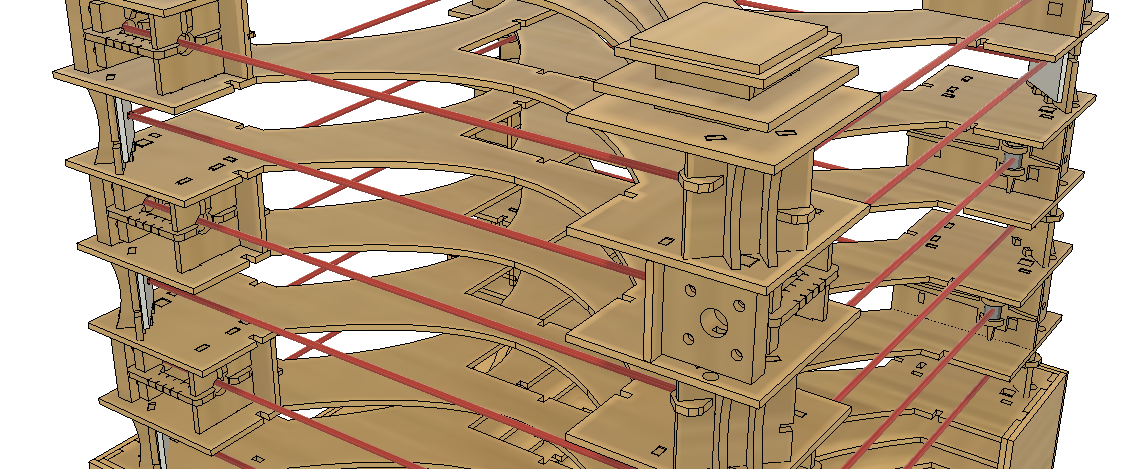
The upright laser harp consists of 12 lasers and photoresistors arranged in six layers. Two mirrors per layer reflect the laser beams to the photoresistors. In the figure, the red arrow indicates how the laser is reflected to the photoresistor and the corresponding pins the laser and photoresistor is connected to. The pins are scrambled up due to the way the wiring feeds down the tower to the Arduino Mega. The lasers can be triggered on and off using digital pins, and the voltage drop across the photoresistors is measured using analog input pins. When the laser is blocked, the resistance of the photoresistor increases and the voltage output drops.
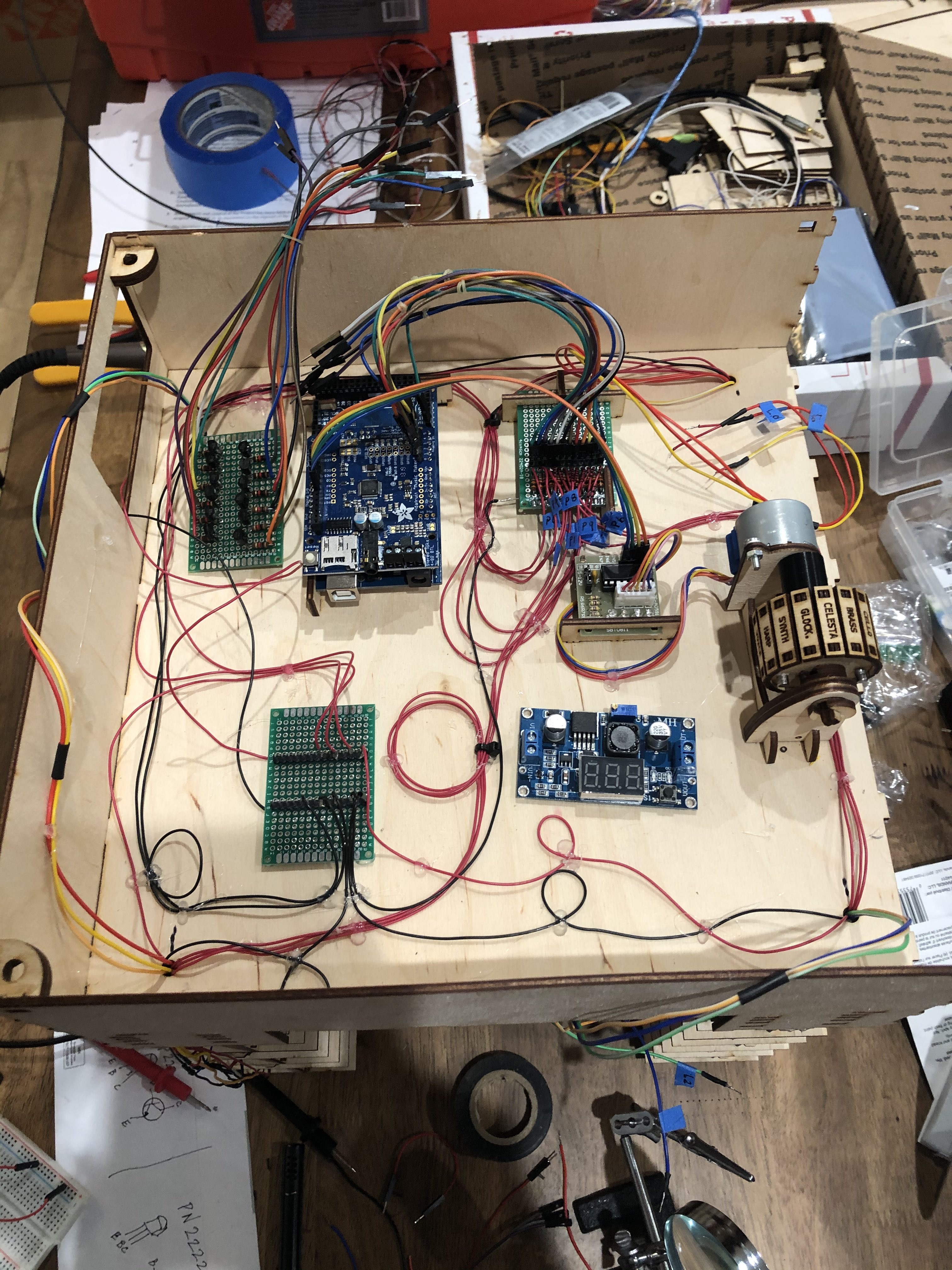
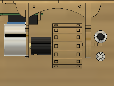
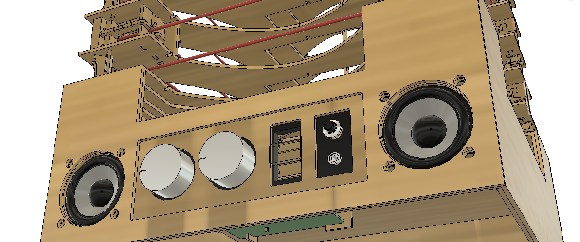
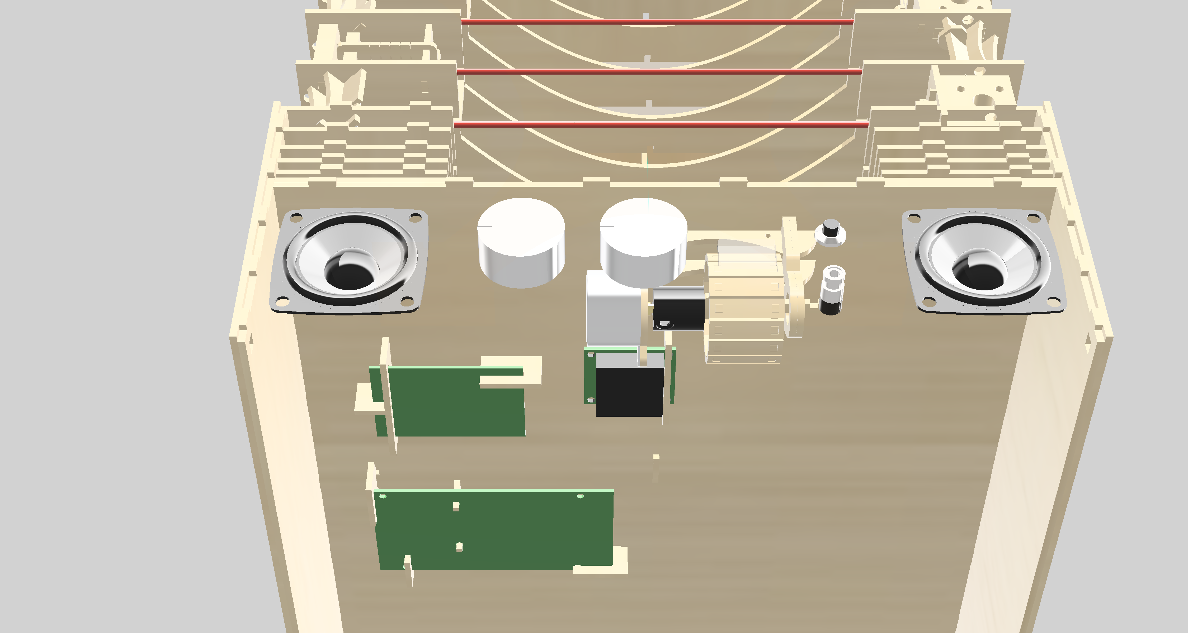
The instrument produces audio output using the incredible Adafruit Music Maker shield. I was so happy to discover this shield, because I can now easily produce audio signals from the device without connecting a MIDI player. Check the link for all the info on how to set up this shield. The shield is run in MIDI mode with the audio output being run to audio jack and speakers. A latched pushbutton turns the speakers on and off. Here is a link to the chip (VS1053b) at the heart of the music maker shield. Page 33 has all the instruments.
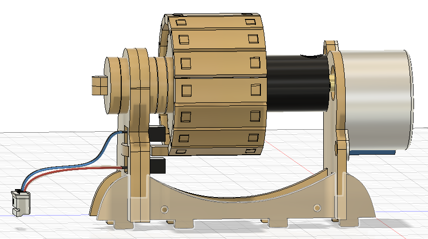
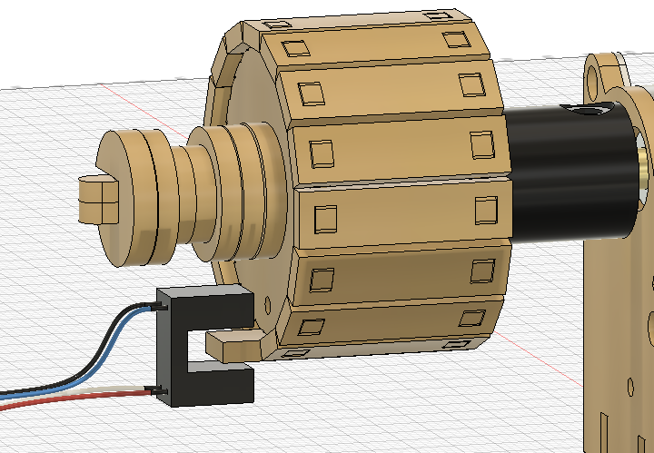
The volume of the device is controlled using a potentiometer connected to the Arduino Mega. The output is read and software updates the volume of the MIDI signal. Finally, the device can also switch between different MIDI instruments. A rotary switch is read and the output is used to update the instrument. I chose to have 16 preloaded instrument selections on the device. The number of instruments is not limited by the Arduino and music shield. There are over 100 options for instruments on the VS1053 chip. I think there is probably enough memory on the mega to store all those instrument codes if you wanted. The selected instrument is displayed on a wheel with 16 spokes. The wheel is turned using a stepper motor, which is controlled with 4 digital pins.


 Dominik Meffert
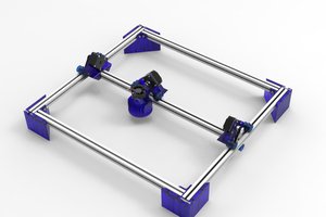
 Jason Cho
 HyperIon
 LesWright
built in diffuser?