 Jonathan Bumstead
The laser harp can cycle through MIDI instrument sounds. I chose to preload 16 instrument labels on the Arduino that would be sent to the VS1053 chip on the Adafruit music maker shield. The number of instruments is not limited by the Arduino and music shield. There are over 100 options for instruments on the VS1053 chip. I think there is probably enough memory on the mega to store all those instrument codes if you wanted.
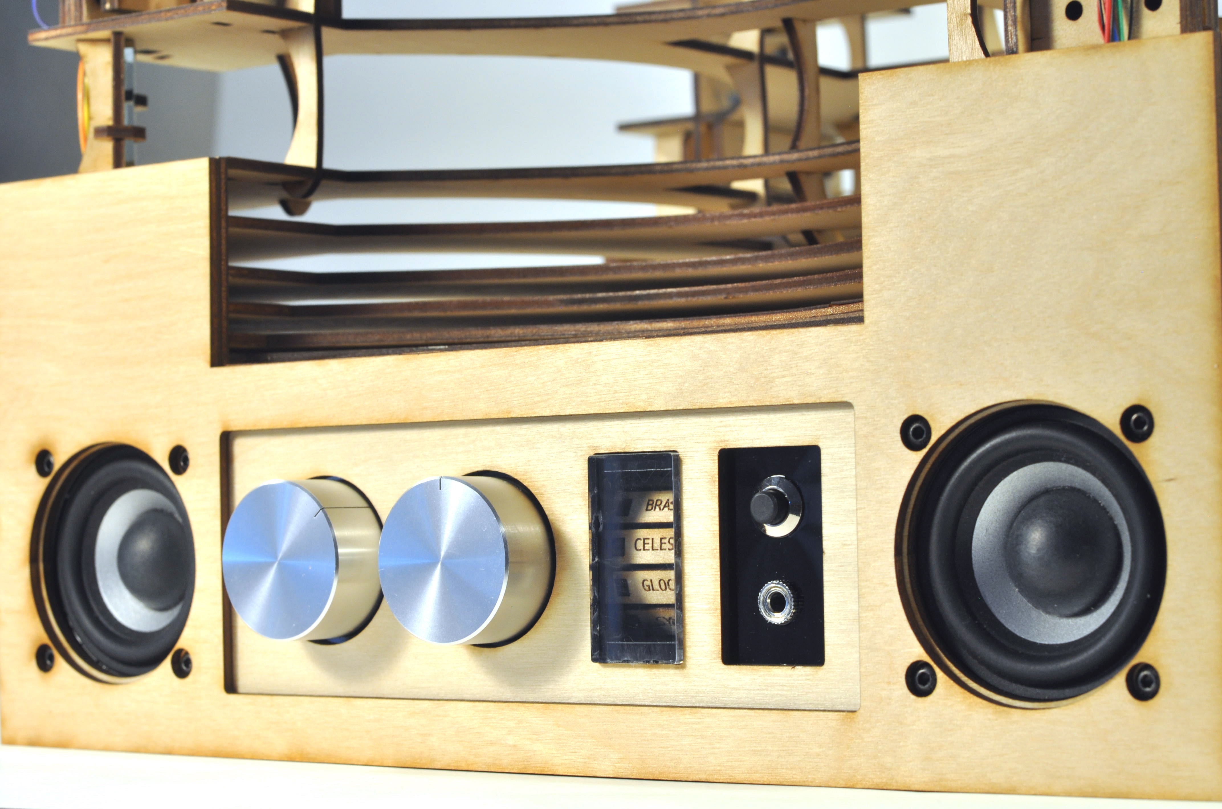
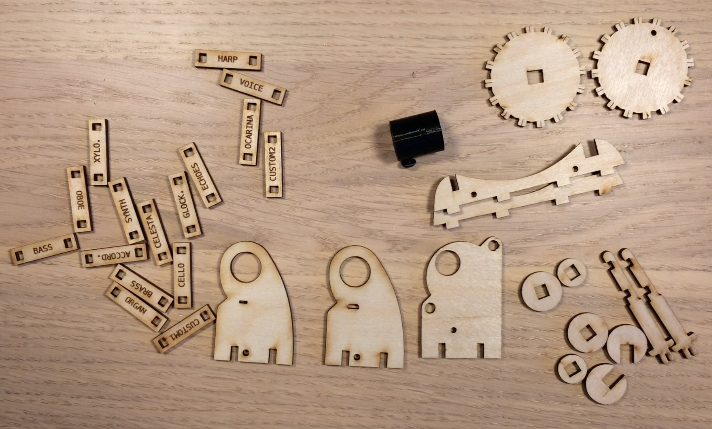
To display the selected instrument, I designed an instrument wheel that rotates. An instrument name is written on each plank on the rim of the wheel. The signal from the rotary encoder changes the instrument and rotates the motor so the user knows which instrument is being played.

The stepper motor is secured onto the mount with two bolts. There is directionality to this mount; see the CAD model gif and video to make sure everything is in the right direction. A 3D-printed motor coupler connects the motor shaft and wheel axle. The two axle pieces are glued together and pushed into the coupler. Then the first face of the wheel (the one with the bigger rectangular cutout) slides over the axle, followed by the second face of the wheel. Some wax may be required because it is a tight fit. The rim of the wheel with the instrument types holds the two faces together. The words will be upside down when viewing the wheel with the first face to the right of the second face.
Next the two parts holding the Hall effect sensor are glued together. The Hall effect sensor is used to determine the position of the wheel. The bipolar Hall effect sensor switches high to low when the magnet field over the sensor changes. Two magnets are therefore placed on the wheel facing opposite directions. The wheel rotates until the sensor reads high and then switches to low. Some offset in steps is then added to position the first instrument at the right position in the display.
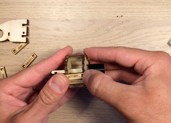
The Hall effect sensor is pushed into place with housing over the middle lead to avoid a short. Check the wiring in the schematic. Now three circular parts slide over the axle so that the axle can turn in the circular hole in the Hall effect sensor mount. Two C-shaped parts are pushed orthogonally into the axle to hold everything in place.
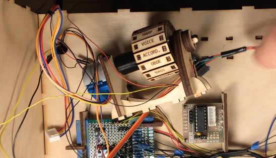
The motor is then connected to the axle via the coupler, which holds a nut and set screw that presses into the motor shaft. Finally, the whole assembly is held together with two spline shaped mounts.
Discussions
Become a Hackaday.io Member
Create an account to leave a comment. Already have an account? Log In.