 Donnie Agema
Details can be found in the links provided.
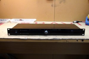
After looking back at the original Elektor project, I became not so satisfied with my results, seeing the original specs claiming a bandwidth of 100 kHz to 1.5 GHz +-2.5dB, which I was not getting even close to. Since I still had 2 unused PCBs from OSHpark, I decided to build another one, keeping as close to the original design as I could. But that did not bring any significant improvement. The Bode plot I saw on the spectrum analyzer suggested to me that the problem part was the FET, so I tried replacin the originally specified BF998 with a CF739, which had better specs in the datasheet as the BF998. That proved to be the right move, giving me a bandwidth of 95 kHz to 1.94 GHz at +-2.5 dB. NOW I am satisfied! Oh, yeah, I also used an SMA connector instead of the pogo pins, allowing me to easily configure it with any probe tip I might end up needing.

 The Reverend
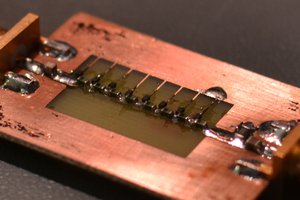
 Logan Cummings
 Mike Kushnerik
 Jon Thomasson
Since you updated the Elektor design, can you publish your updated PCB layout?
What probes could you connect to the SMA connector instead of the pogopins? Any examples?