 Daniel
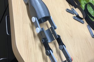
The end result should work like this:
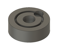
The Fusion 360 script works in a similar fashion as a human designer will design the bearing:
- Check the input parameters are correct.
- Draw the inner and outer circles and extrude them (create new body operation).
- Draw the gap circle and extrude it (cut operation).
- Draw the BB ball circle and revolute it (cut operation).
- Draw the insertion and extraction circles and extrude them (cut operation).
The execution of the script will result into two parts being generated (the inner and outer part of the bearing).
 After converting those parts into STL files and 3D printing them, it is time to assemble it together with some BB balls, giving as a result the following bearings:
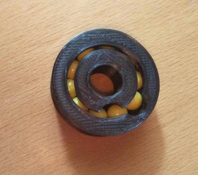


 ben.brochtrup
 Kevin Harrington
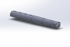
 Alan Chambers
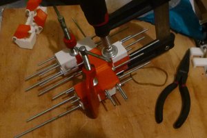
 Nelson Phillips
Hello,
I've added some changes.
https://github.com/takeru/BBBallBearingGenerator/commit/40692ed56293c8d2c8b65ae3ba4d56c37f671157
"overhang_angle" for print without supports.
"join bodies" for to export one STL file.
My ball is 5.9mm. dbb = 6.2 or 6.1 is best.