Jacob Hahn
-
LIF: Saving my ROM
09/08/2019 at 05:37 • 0 commentsTonight I was looking around eBay to check for low prices on parts I need to build my SBC, and I came across a socket called a "Low Insertion Force" socket. These sockets are built for prototyping or chips that are made to be removed often and they are much cheaper than ZIF sockets. The standard IC sockets I use hold onto the chips inserted into them very tightly, which is great for any that I don't have to remove, but in my case is bad for my ROM IC. I need to remove it and replace it many times to experiment with code, so the tight grip could eventually start to cause damage from stress to the board and socket. With these LIF sockets, I can hold my IC in tightly and remove it easily when I need to, and I can fit them into a standard socket so I can remove them when I have my final code. I went ahead and bought 10 of them for less than a dollar a piece.
-
Progress Update: More than a Basic Success
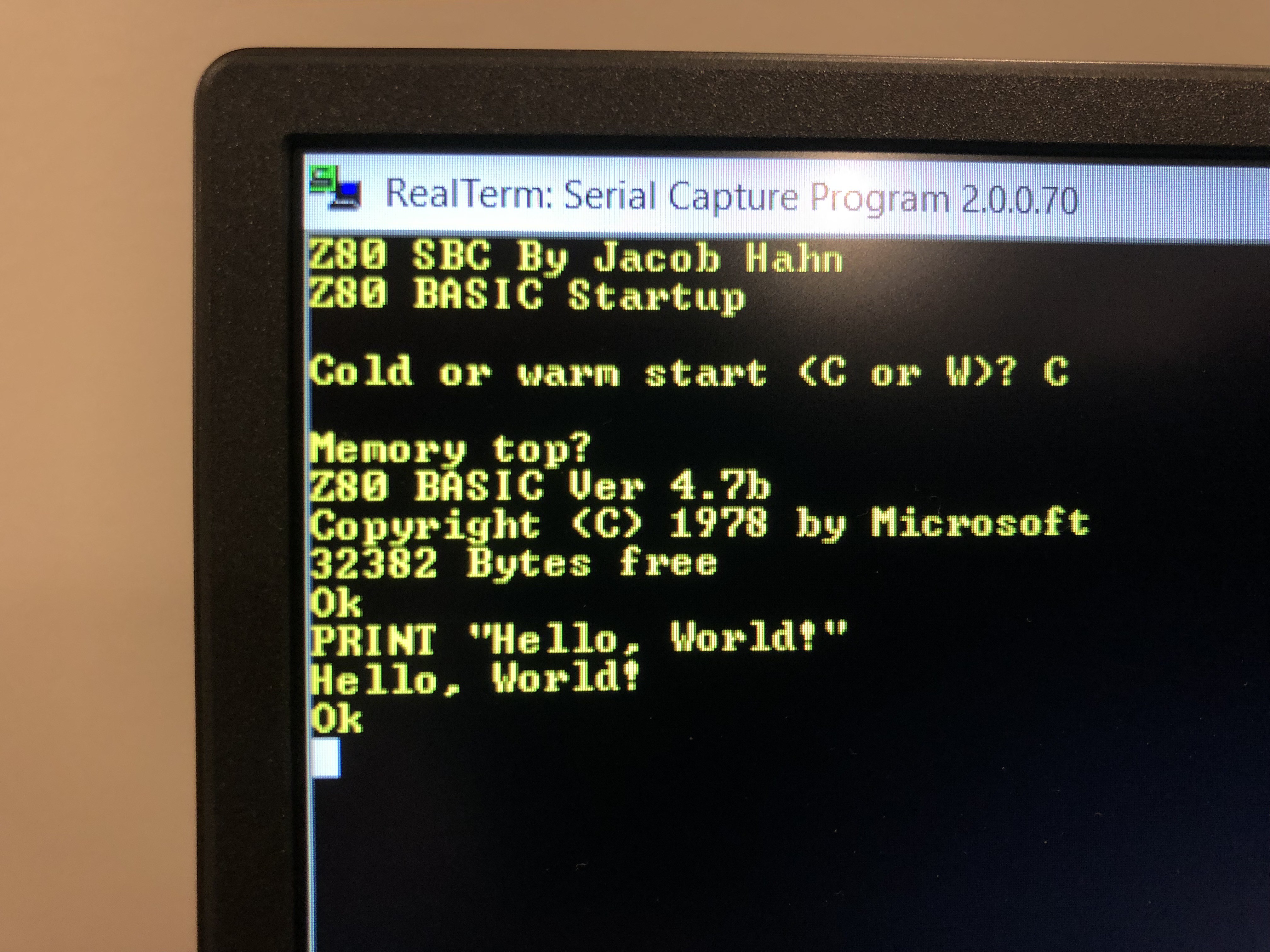
09/01/2019 at 02:49 • 0 commentsAfter much testing and thinking, I've (finally!) found the issue in my project preventing BASIC from running properly.
After the test program worked, I reflashed BASIC to the EEPROM and started the SBC with it. To my surprise, it booted just fine, and BASIC worked as expected. However, when I clicked the reset button on the board to test if it would work a second time, nothing happened. I kept pressing it, and after about 10 tries, it finally reset properly. Strange. The last thing that I would have expected to have caused all of the issues I faced was a faulty push button. So, as confirmation, I attempted to reset the board by shorting the reset pin to GND, and it reset immediately every time I did it. Well, that explains it.
![]()
NASCOM BASIC running on SBC V2 Next up, I'm going to work on a way to test the CTC and do some basic timing operations.
-
Progress Update: Debugging the Hardware
08/31/2019 at 02:27 • 0 commentsTonight, I got my multimeter and tested my prototype. Surprisingly, I couldn’t find any hardware faults, leaving only software as the culprit. Of course, this confused me, as the exact program had worked on my PCB V1.1.
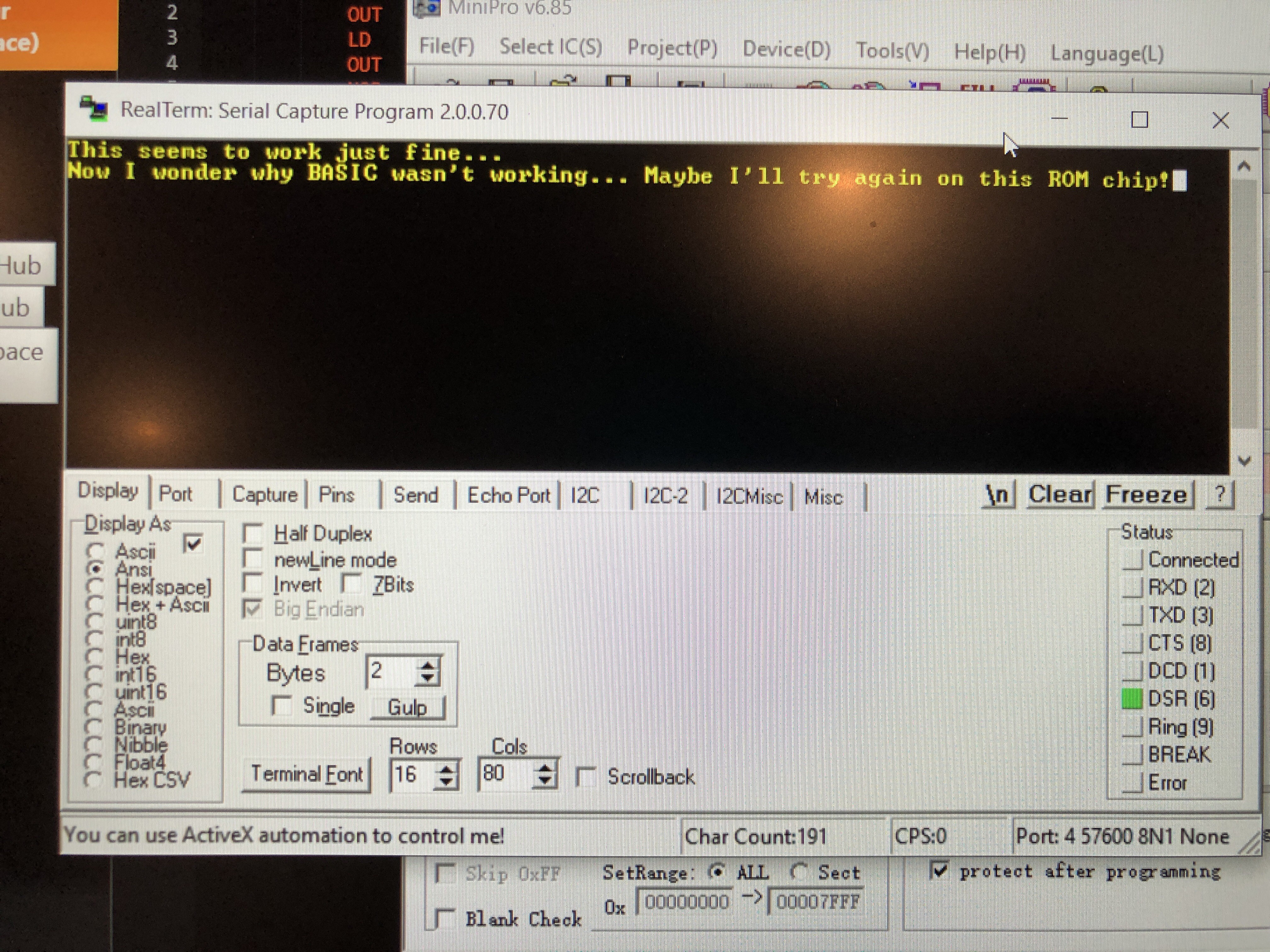
So, as a quick test, I wrote a little assembly software that would just send back whatever you typed over serial. After plugging the board in and typing a few characters, I found that it worked flawlessly! In my mind, this is a success: it shows that software, although simple, does run as I would expect it to while interfacing with the DART.
![]()
The working test program running on SBC V2 Finding this program working, my next step is to flash BASIC to the ROM chip and try to load it again. If it doesn’t work, I’ll have quite a bit of work to do.
I’ll likely have an update tomorrow.
![]()
-
Progress Update #1
08/30/2019 at 01:49 • 0 commentsHey everyone,
I just thought I’d go ahead and give a quick update on how things are going with the project. Just tonight, I received enough parts to be able to make 2 more PCBs. I still haven’t been able to grab my multimeter to diagnose the non-working prototype, but I should be able to have it by tomorrow evening and test the board then. I’ll also take some time this weekend to solder at least one of the new boards and test it out.
On another note, thanks for 10 likes. It might not seem like much, but as a sophomore in high school it’s more than I was expecting. I originally posted this project here to have a personal log that I could look at in the future and share with anyone interested. It’s completely outside of school and as such I need to be able to keep tabs on where I go with it, along with balancing time spent on it with schoolwork. It’s been an amazing way to learn about the workings of computers so far, along with being a fun hobby.
Yesterday, I added a header in the details section for future plans. They’re goals that I want to try and work towards, and while I may not get to all of them, there are a few in there that I really want to try and do.
Check back in a few days for when I finish soldering!
![]()
-
First PCBs and testing
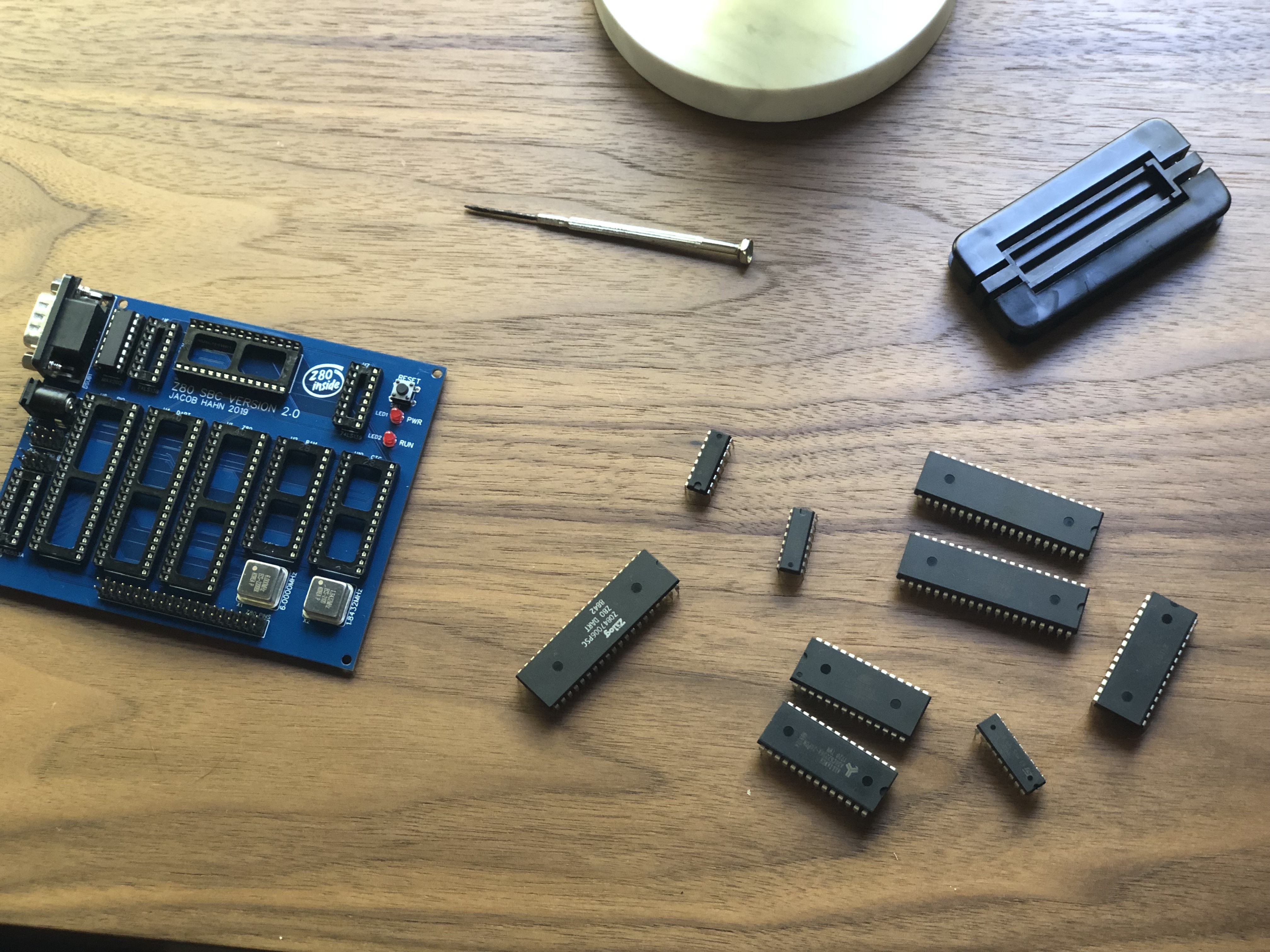
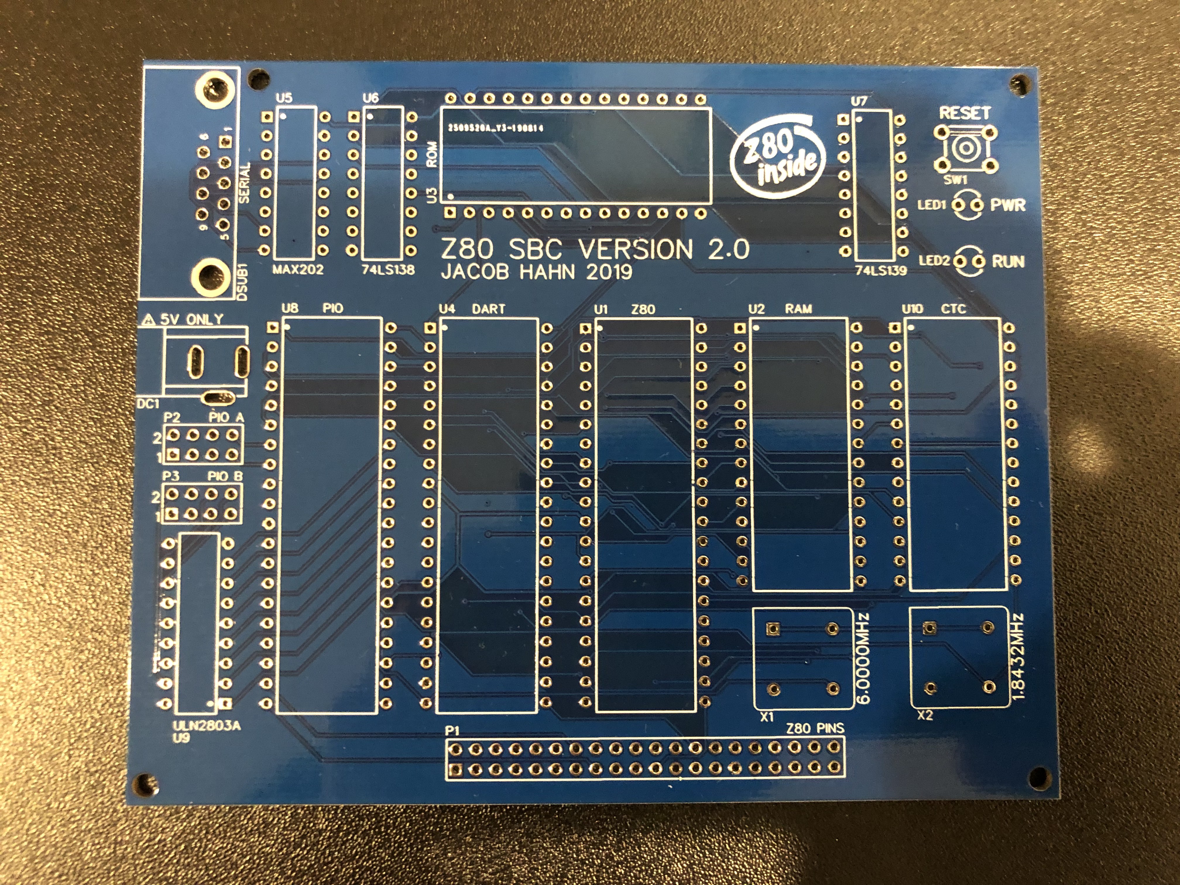
08/27/2019 at 04:56 • 2 commentsA few days ago, I received an order of Z80 SBC PCBs for prototyping. I’ve been spending the past few days finding components and soldering, but I finished a board today.
![]()
One of the PCBs I had made Unfortunately, I made the mistake of not soldering the large ground terminals of the serial port, thinking I wouldn’t stress the port enough to cause damage. Of course, once I plugged in a serial cable, the port flexed slightly, ripping the pad of pin 5 (ground) of the port off of the board. When I plugged the board in to test the output of BASIC, I got a few recognizable words but with lots of gibberish mixed in. I went ahead a used a enameled wire to connect pin 5 to a different ground pad, but the result was the same, so something else must have happened during the process of soldering or from the port damage.
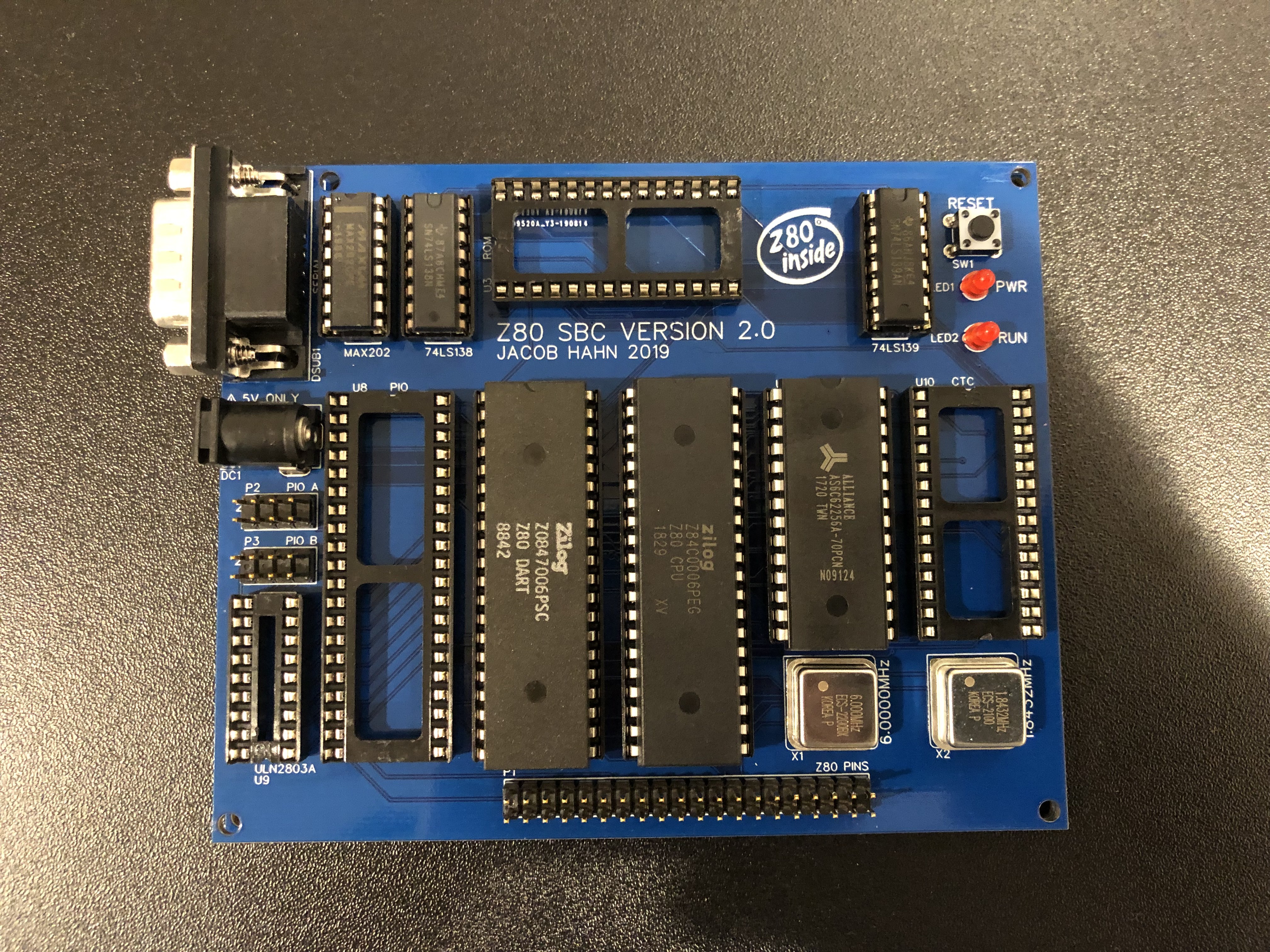
![]()
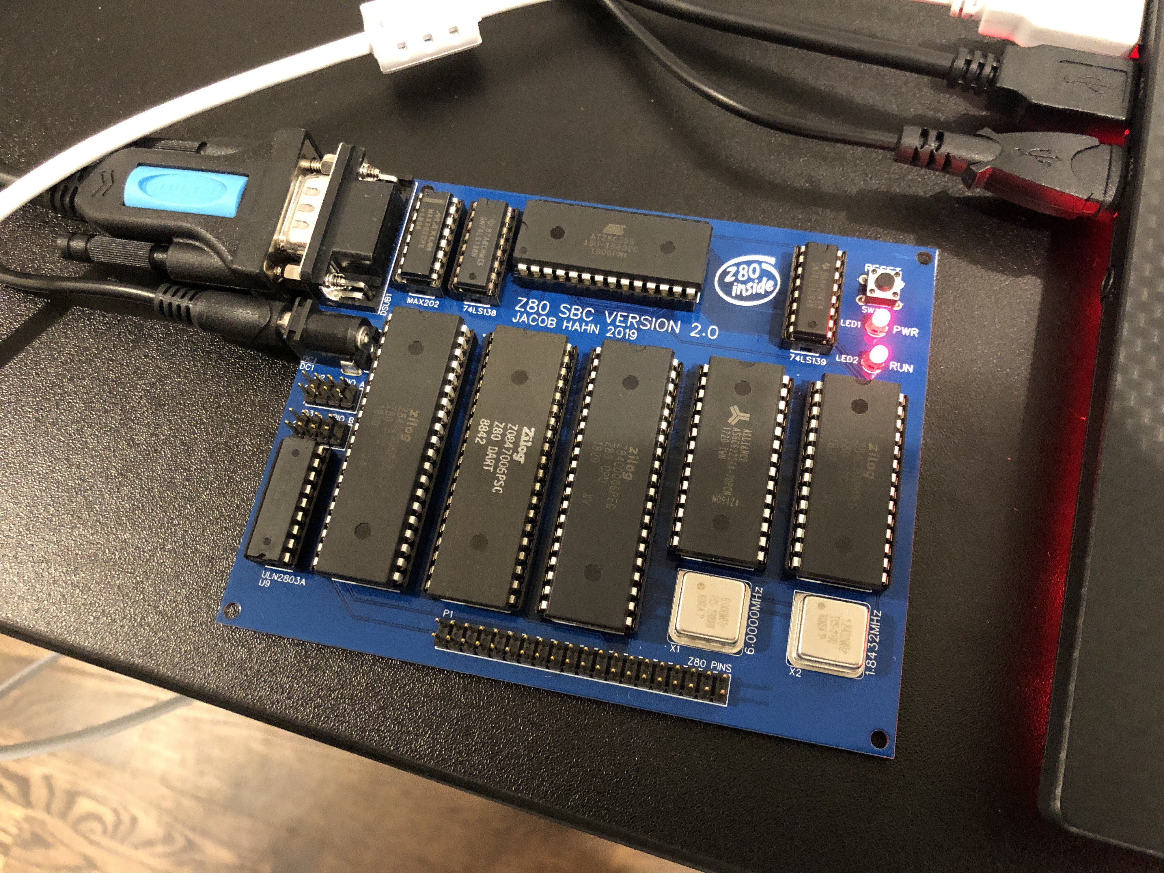
A PCB with everything soldered and a few ICs I checked the board thoroughly for any damage, such as broken traces, but could only find some scraped solder mask here and there on the back. Nothing major, and certainly nothing that would affect operation.
Luckily, I already have some new components ordered and I should be able to have a new board made by this weekend.
I’m also working on updating the PCB layout a bit for v2.1, including moving the ROM to the right a bit (so that I can use my IC prying tool with it!), a larger ground trace on the transistor array, and extended PIO pins. Thanks for the ideas, @Ken Yap!
Stay tuned, as I’ll be adding details and info throughout the week.
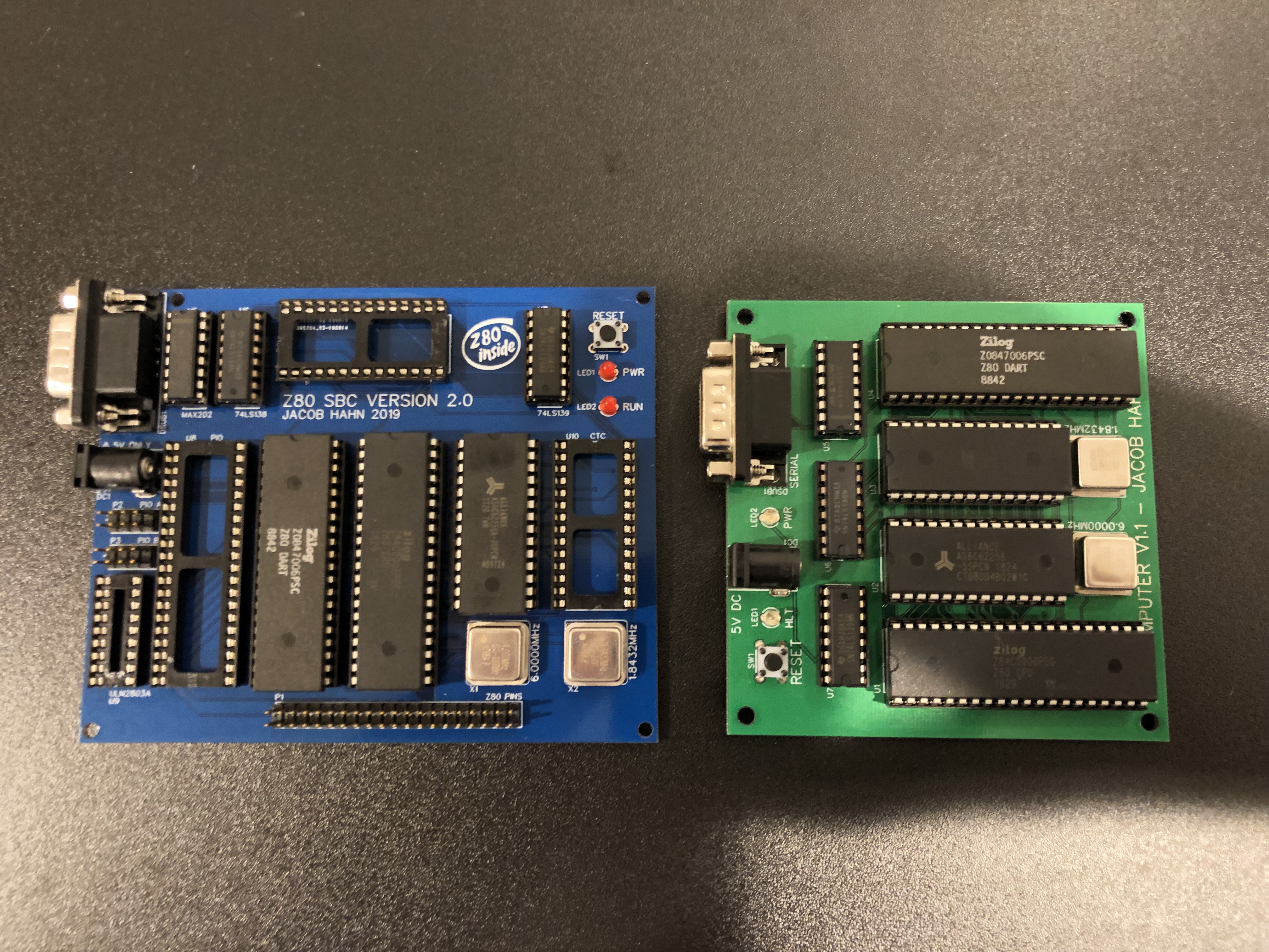
![]()
SBC V2 alongside SBC V1.1, my current working version
ZTO-80 Computer System
A powerful Z80 computer built around a highly expandable central bus design