 rand3289
How it works
Fibergrid hardware consists of two parts: a lightsource and a camera with an enclosure. They are connected to 3D printed sensors by inexpensive plastic fibers. The light source shines light on a grid with exposed fiber ends. Fibers transmit light to your light blocking sensors. What light remains is picked up by another fiber that transmits it to the camera enclosure. Camera software running on your PC, laptop, tablet, phone, Raspberry PI or anything that has or can interface with a camera converts each incoming fiber's light to a number.
You design the sensors based on the principle of blocking light. Alternatively LEDs can be placed within individual sensors. In either case, FiberGrid is able to sense how much light a mechanical sensor blocks and give you a value in software as a continuous range not just an on/off flag.
A single FiberGrid camera can simultaneously read values from HUNDREDS of "analog" sensors. Many more than the number of ADC channels in any MCU! This eliminates the need to communicate among multiple MCUs. You do not need any band or low pass filters as you would for some ADC channels. No debounce circuits for interrupt triggering pins. No scheduling (waiting) for ADC completion in firmware. Read-modify-write problem will not haunt your in your sleep. No back EMF on your power rail to deal with. No worrying about induced currents. Schmitt trigger is gone from your vocabulary. You no longer care about TTL and CMOS logic difference. Floating open collector who? Pull up, pull down, reference voltage, resistor ladder what? Time the discharge of a cap through a pot on a digital pin never again. No more explaining all of the above to ten year olds in STEM, just give them a glue gun and let them make stuff with sensors! Don't have a USB cam and a computer or a Raspberry PI? Use your phone - those cameras are pretty good and OpenCV is supported on Android!
If you want to make suggestions or need help, reach out to me at toAndrey(at)yahoo(dot)com. Also I place this project or any code associated with it into public domain so feel free to modify it in any way, shape or form. However I make no guarantees of any kind. Use it at your own risk. Any information provided here is for educational purposes only! Do not blame me because your security system utilizing this technology failed and your Ferrari was stolen.
How the software works
There are two parts to FiberGrid software. FiberCal is a calibration program that finds centers and bounds of the fibers in the camera's visual field and saves this information in a file. Second is the FiberGrid "driver". It uses the config file and provides a simple API for reading your sensors.
The location of the fibers should never change if you have made the hardware device properly. This allows me to separate the driver and calibration software for two reasons. Detecting fibers can be done more accurately with human interaction. The second reason is portability. The driver could probably be written in 50 lines of python or java or C# code or re-written in C++ without using OpenCV. Meanwhile the calibration utility does not need to change. Let me re-iterate: once you know the locations of the fibers in your device that hopefully will never change, you can write a program to capture images and covert pixel brightness to values using your favorite programming language in a few lines of code!
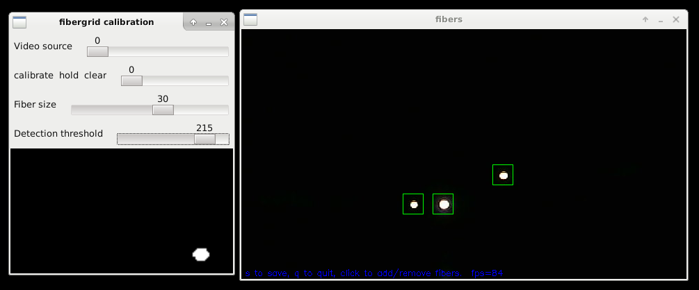 Here fibergrid calibration utility (fc) is detecting 3 fibers in the grid. Image on the left is a closeup of one of the fibers. You have an ability to change the fiber detection threshold, fiber visual size and add or remove fibers manually by clicking. You should configure fibergrid to collect light anywhere from 9 to 100 pixels for each fiber (indicated by a green square). Fiber size is the square side in pixels. Save the config file by pressing "S"! Software is available here: https://github.com/rand3289/FiberGrid
How the sensors work
All FiberGrid sensors block or capture light. For example, an optical encoder is one type of sensors that block the light. I am currently working on a rotary optical encoder for FiberGrid. (see project logs) Fibers can also be used as a compound eye to capture ambient light.
Try placing one fiber from the light module and another fiber from the camera into each side of a thin drinking straw or fiber cladding. While watching the cam on the screen, push the fibers in and out or bend the straw. Notice how the brightness of one dot on the screen changes. You've just made your first sensor.
fibergrid_sensor1 in the 3D model pack uses a piece of flat polarized plastic (film) from disposable 3D movie theater glasses to make rotation sensors. It has two small pieces that spin relative to each other. When polarization of the pieces is at 90 degrees they will block a lot of light coming from the emitter fiber. (see build instructions)
As you can see, It is easy to make linear/rotary position sensors. Measuring force is harder. It requires as little displacement as possible and stability over a wide temperature range. Making intrinsic fiber optic strain sensors is difficult! In addition, currently FiberGrid does not perform spectral analysis of the light. It measures the total amount of light received. Here are the alternatives for creating force sensors that come to mind:
* Very stiff position sensors.
* Stiff compliant semi-transparent material / 3D printer filament.
* Stiff reflective material that changes the amount of light reflected when bent.
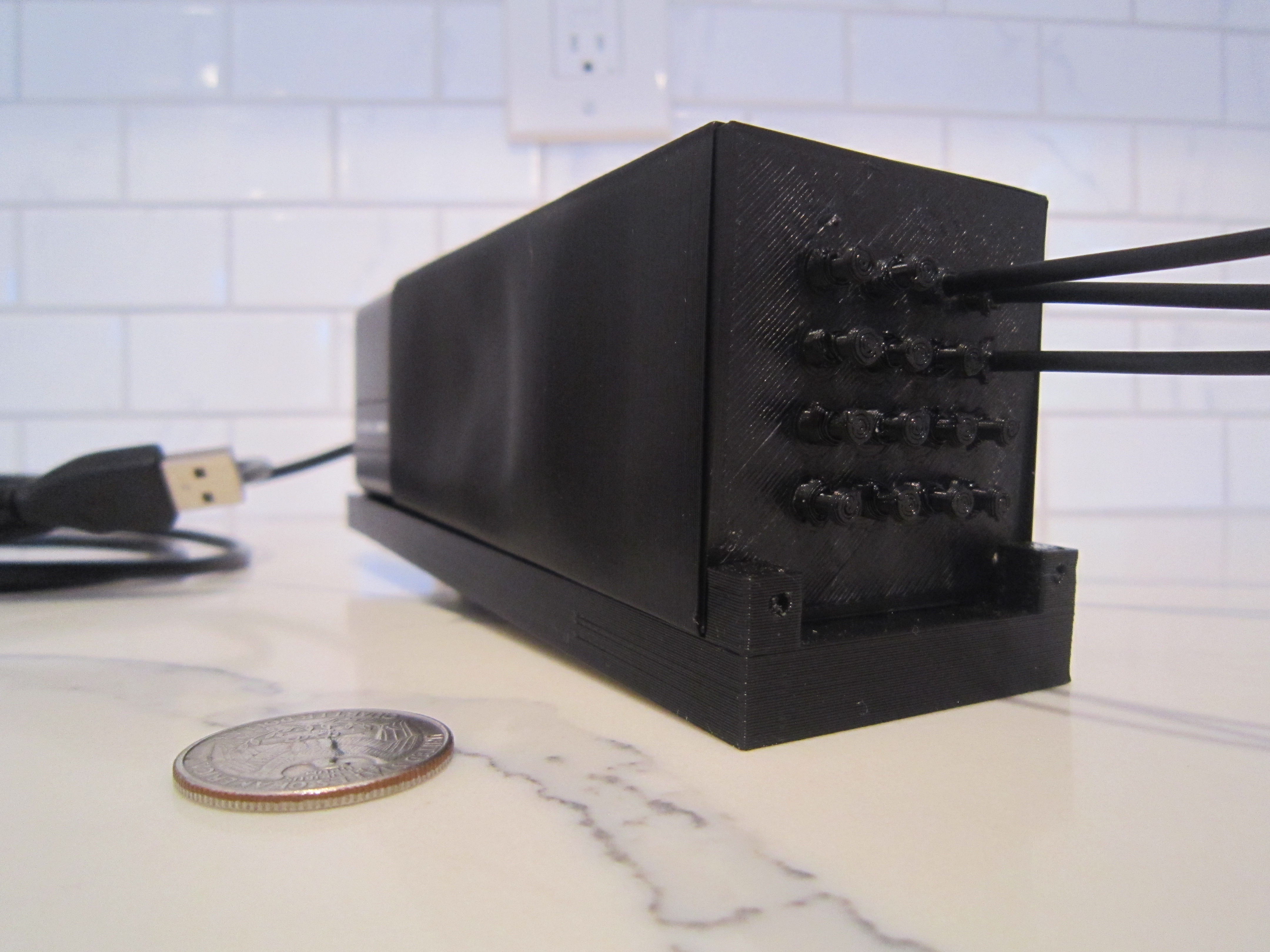
16 connector grid with 3 fibers and 13 shunts plugged into a prototyping grid.
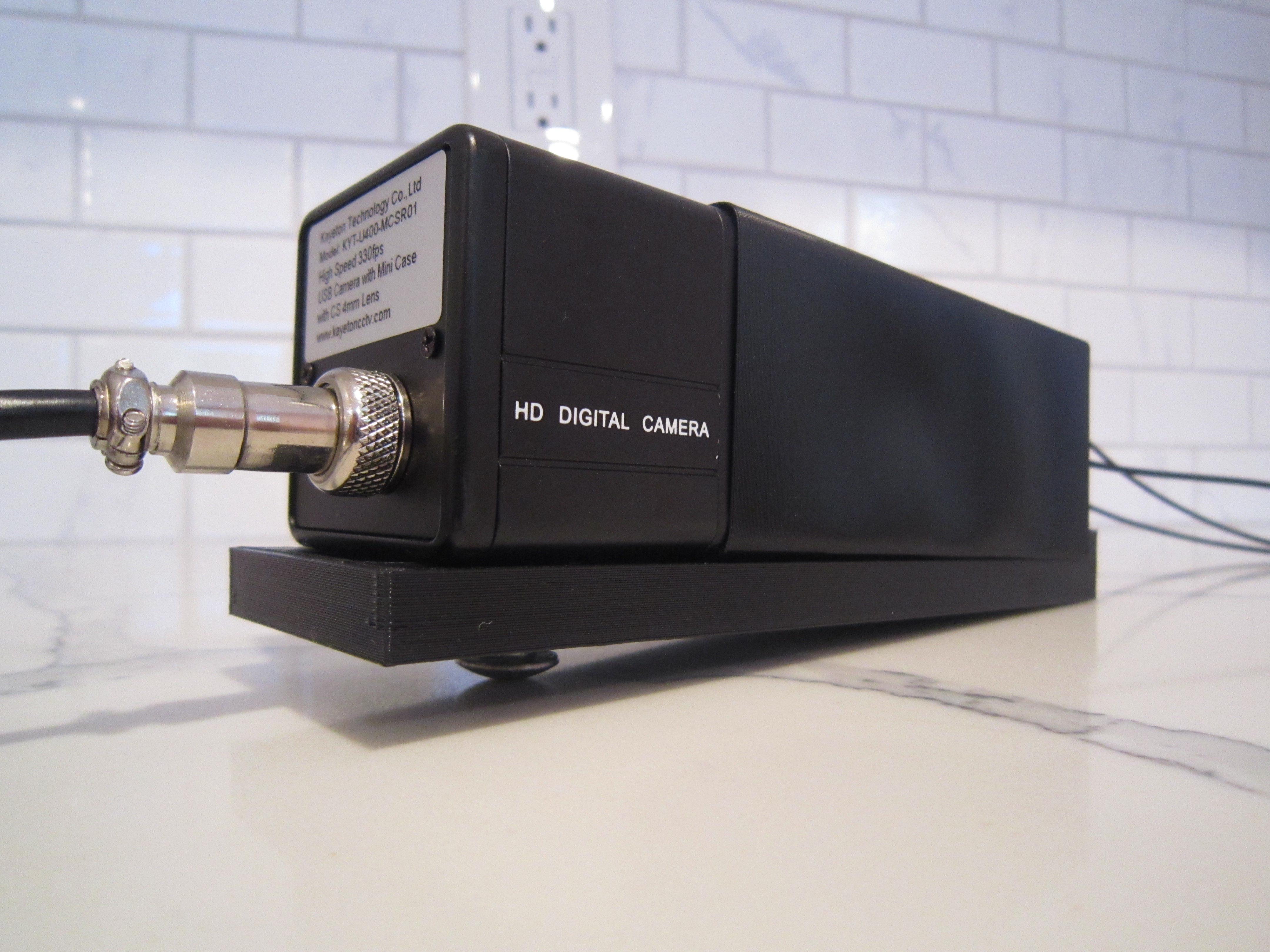
Shroud is fitted around the grid and the camera. Camera slides forward to keep it from moving.
Camera is secured to the "bench" with a bolt.
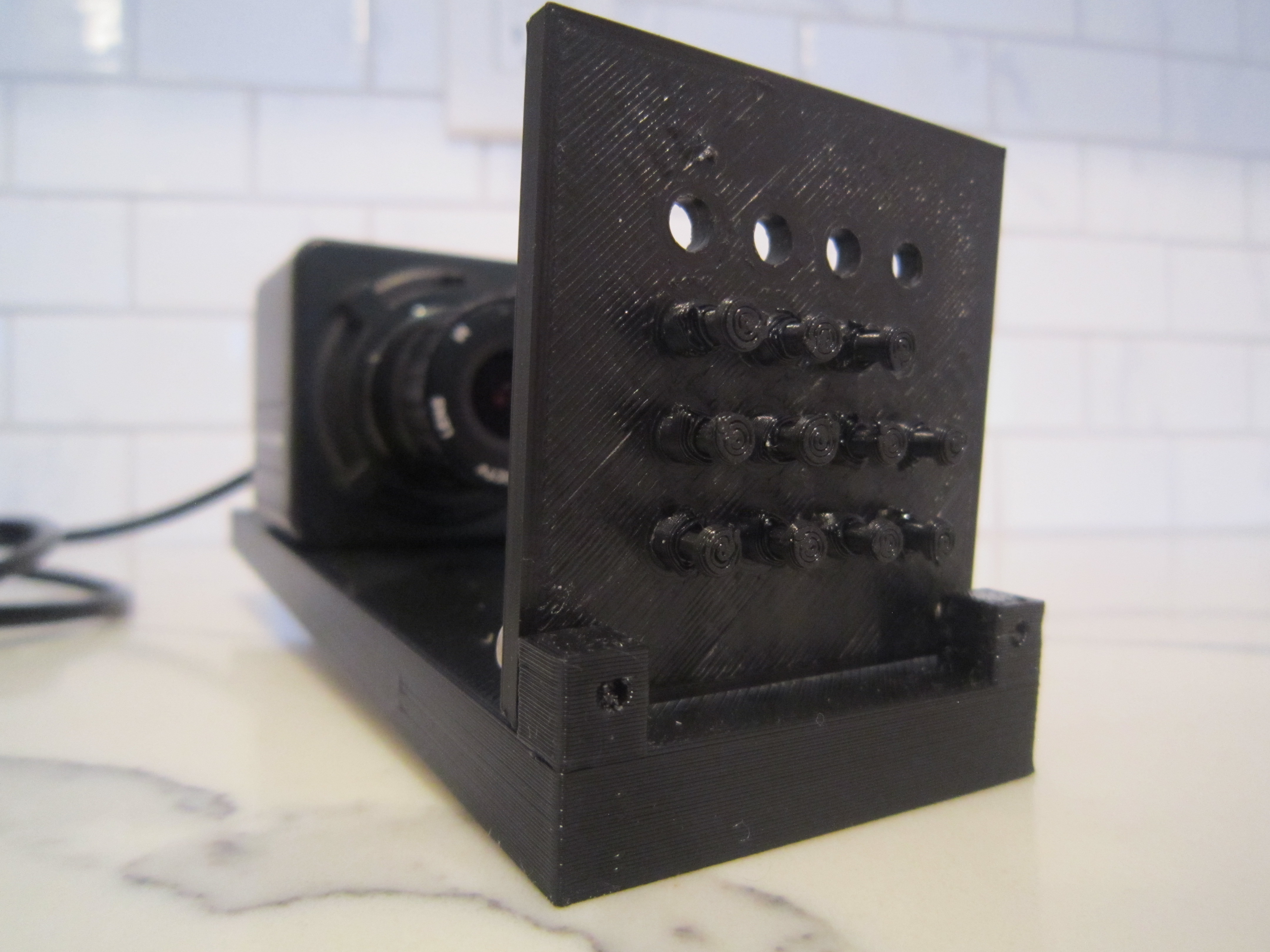
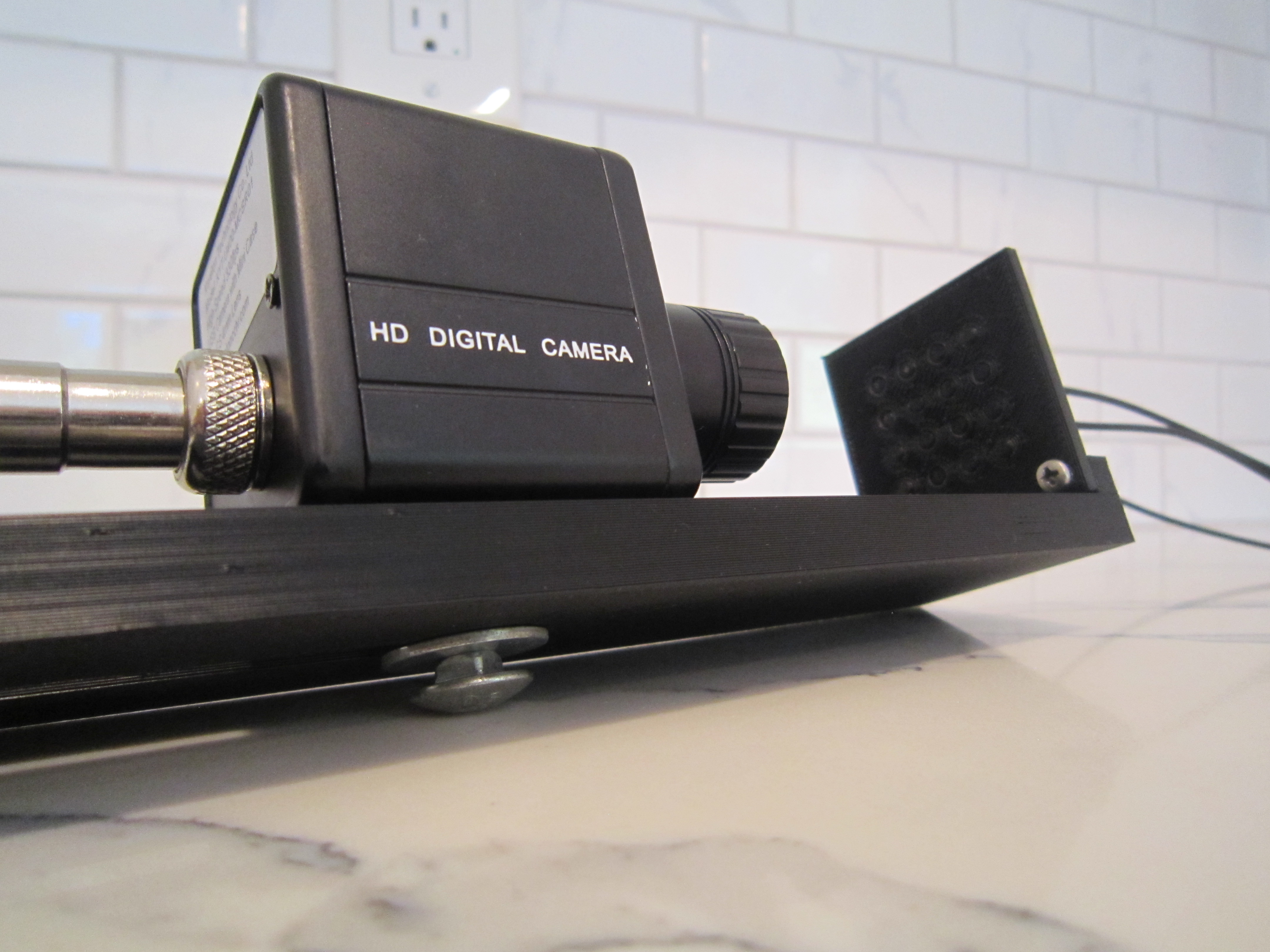
Camera looking at the prototyping grid with 4 plugs removed on the top row