 Blecky
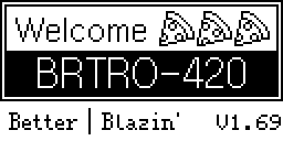
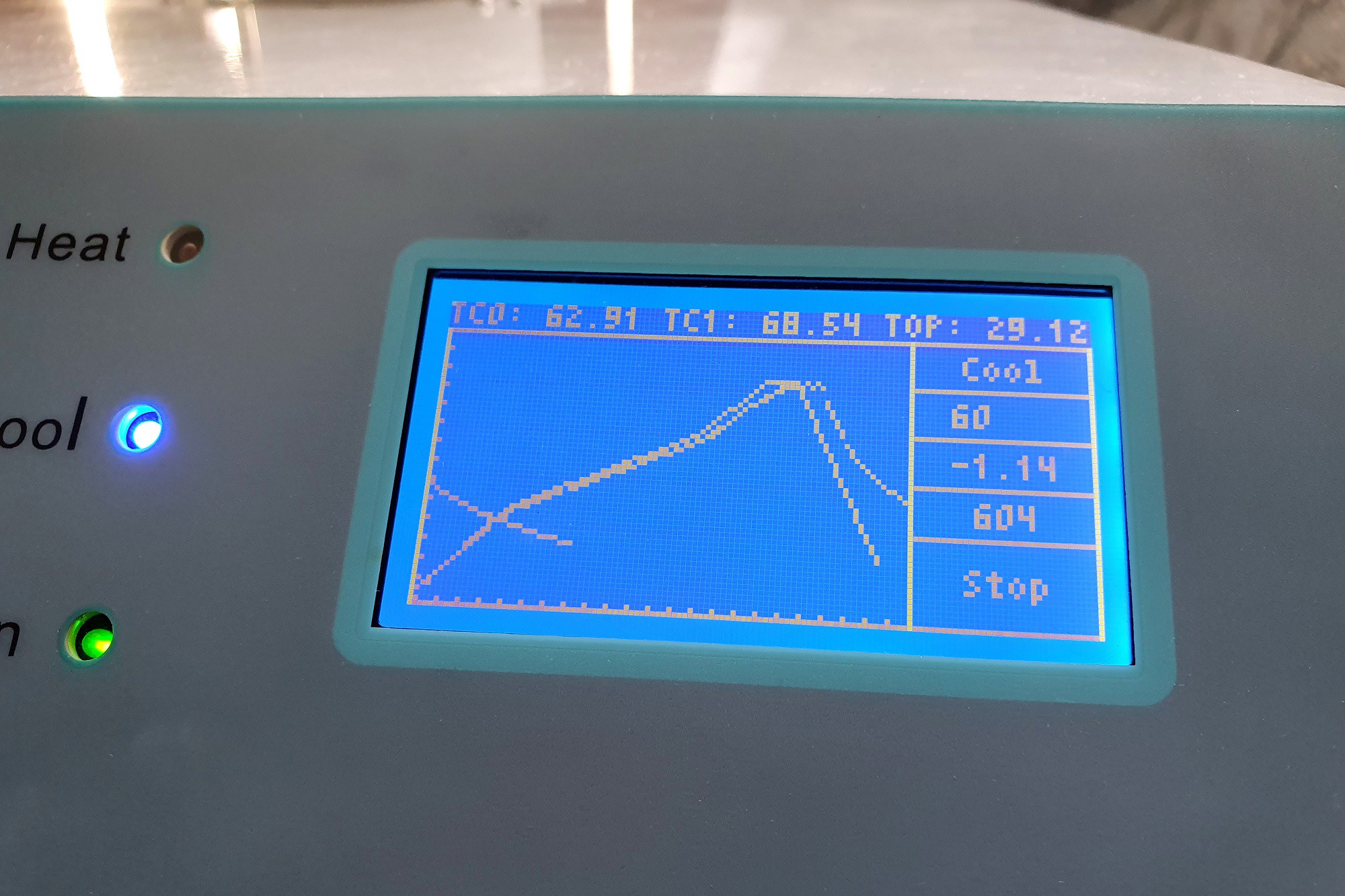
To this:
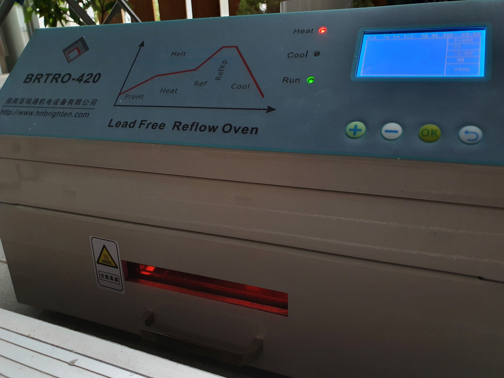
This oven has a few unique features over the popular T-962 oven, which makes it slightly more desirable if you don't mind the higher cost:
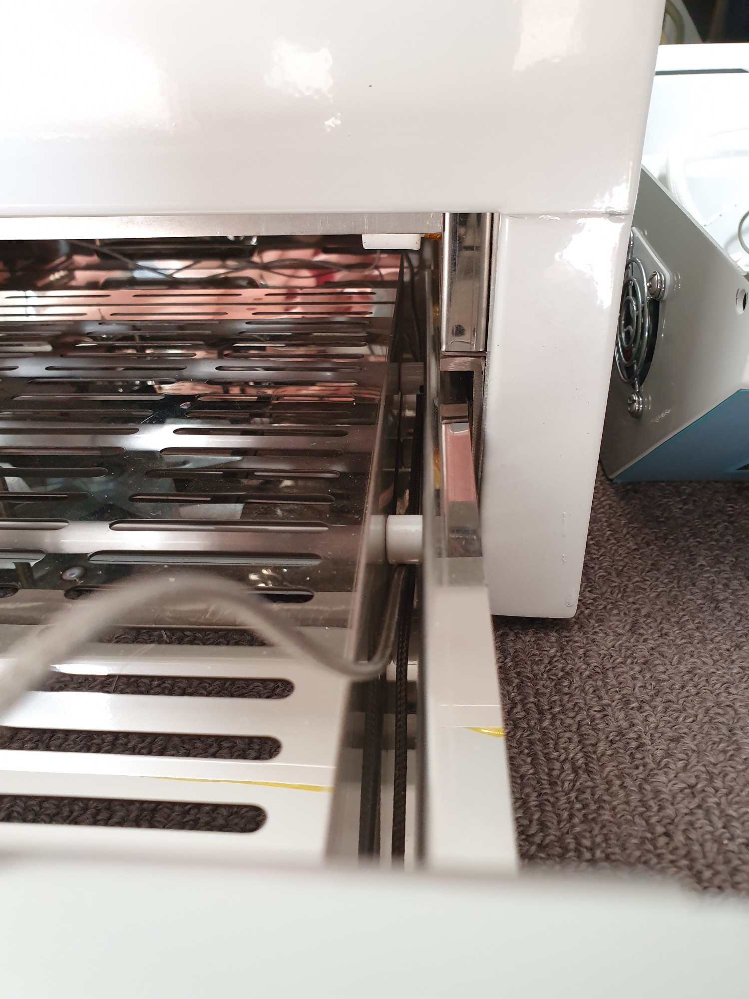
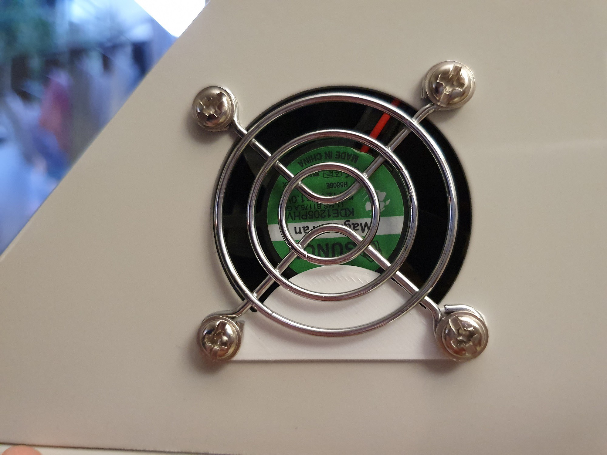
- an internal convection fan built in.
- fume exhaust system which you can vent outside.
- insulation and thermal tape is actually decent, so it doesn't give of nasty smells during operation.
- overall build quality is much better.
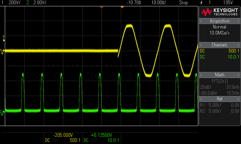
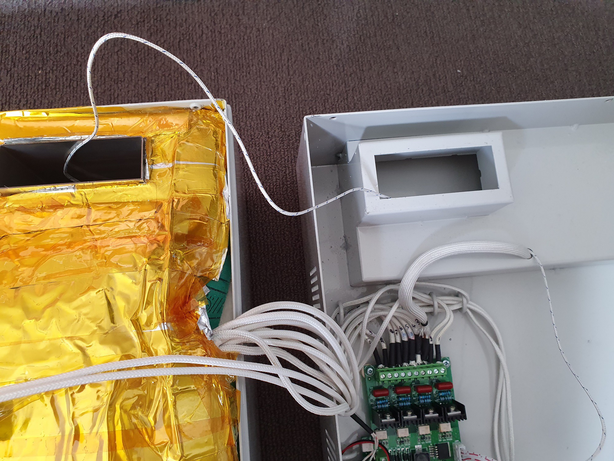
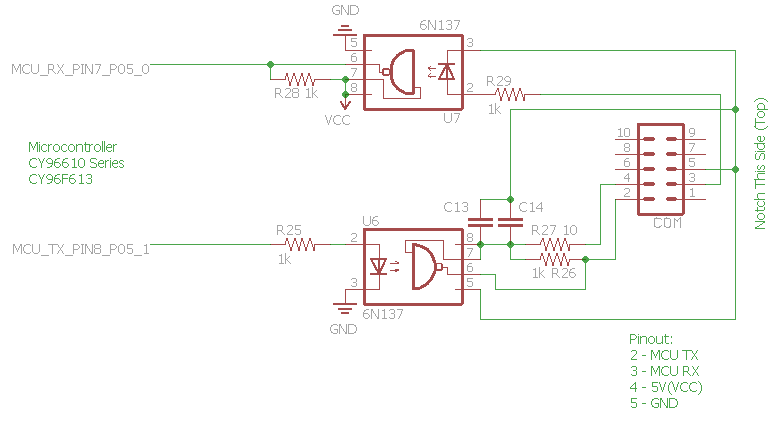
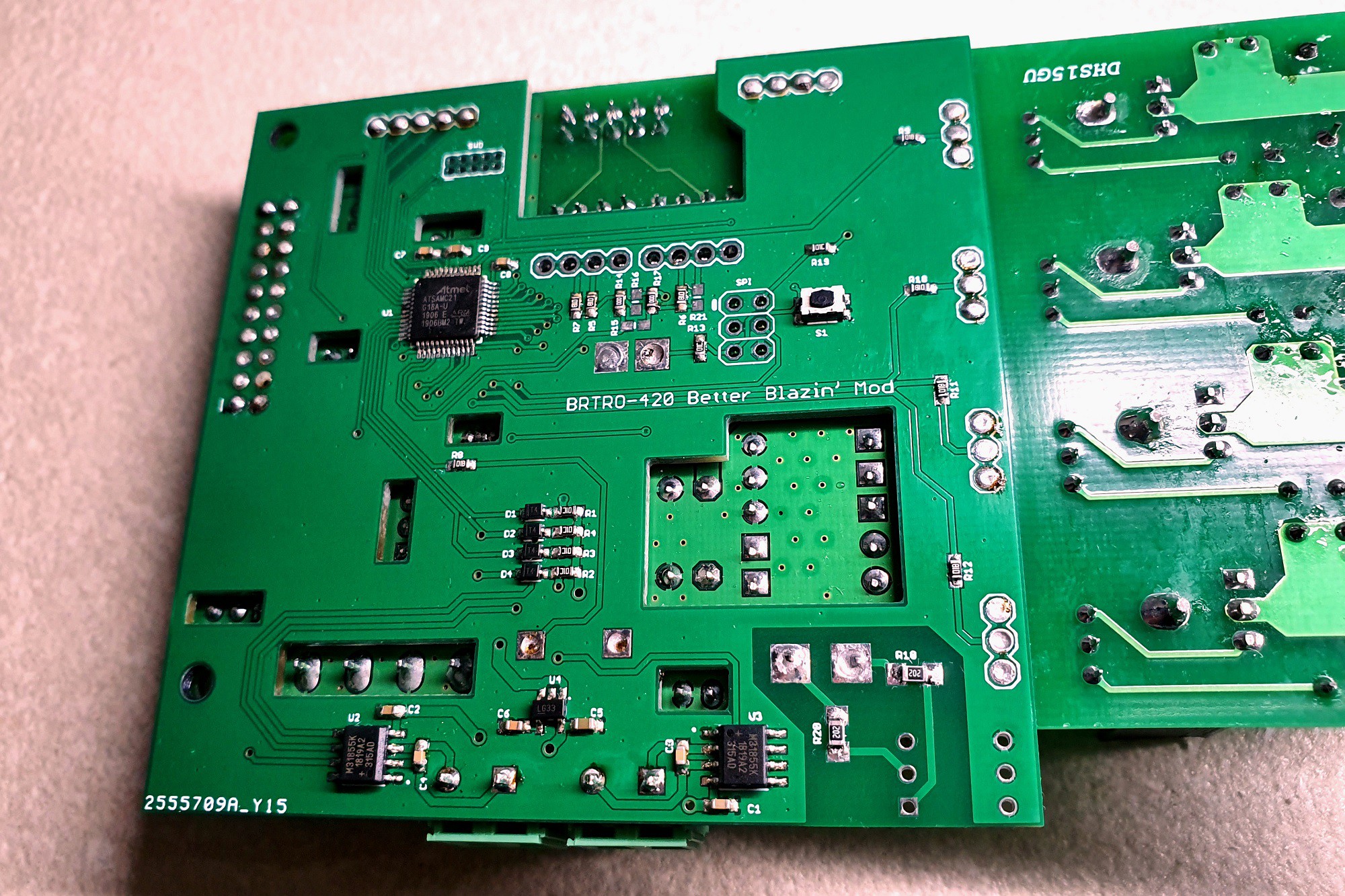
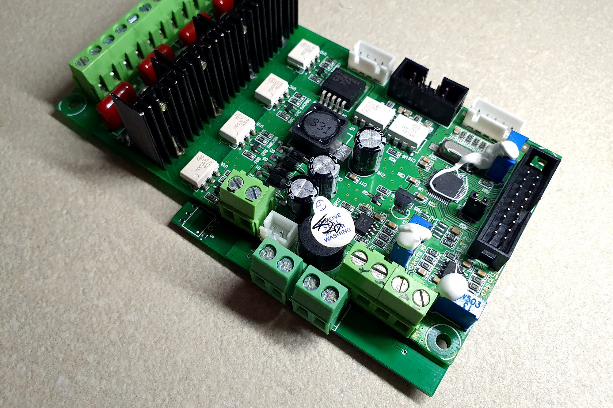
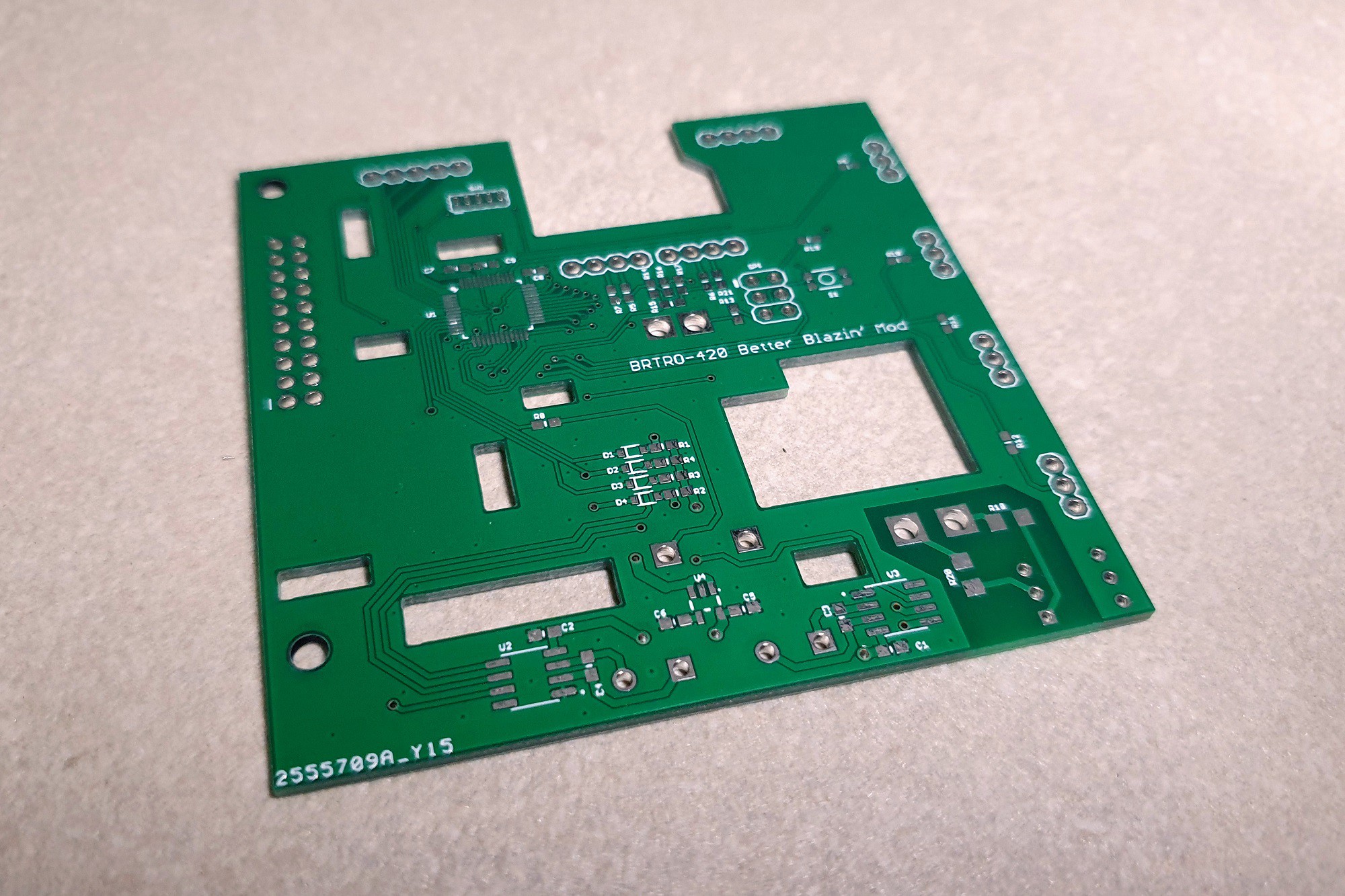
However, unlike the Unified Engineering mods to the T-692, the BRTRO-420 is slightly more difficult to modify, mostly due to the unobtainium build chain for its microcontroller along with a few other design issues such as a poor and noisy thermocouple interface. So the decision was made to spin up a mod board that can be soldered to the bottom of the existing board.
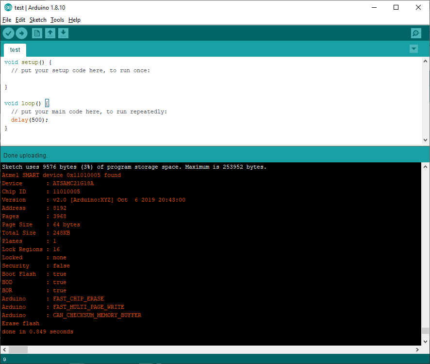
All the firmware sources and board files are here.
All code, documentation and design on these project pages are licensed under the GNU General Public License (GPL) unless otherwise stated.
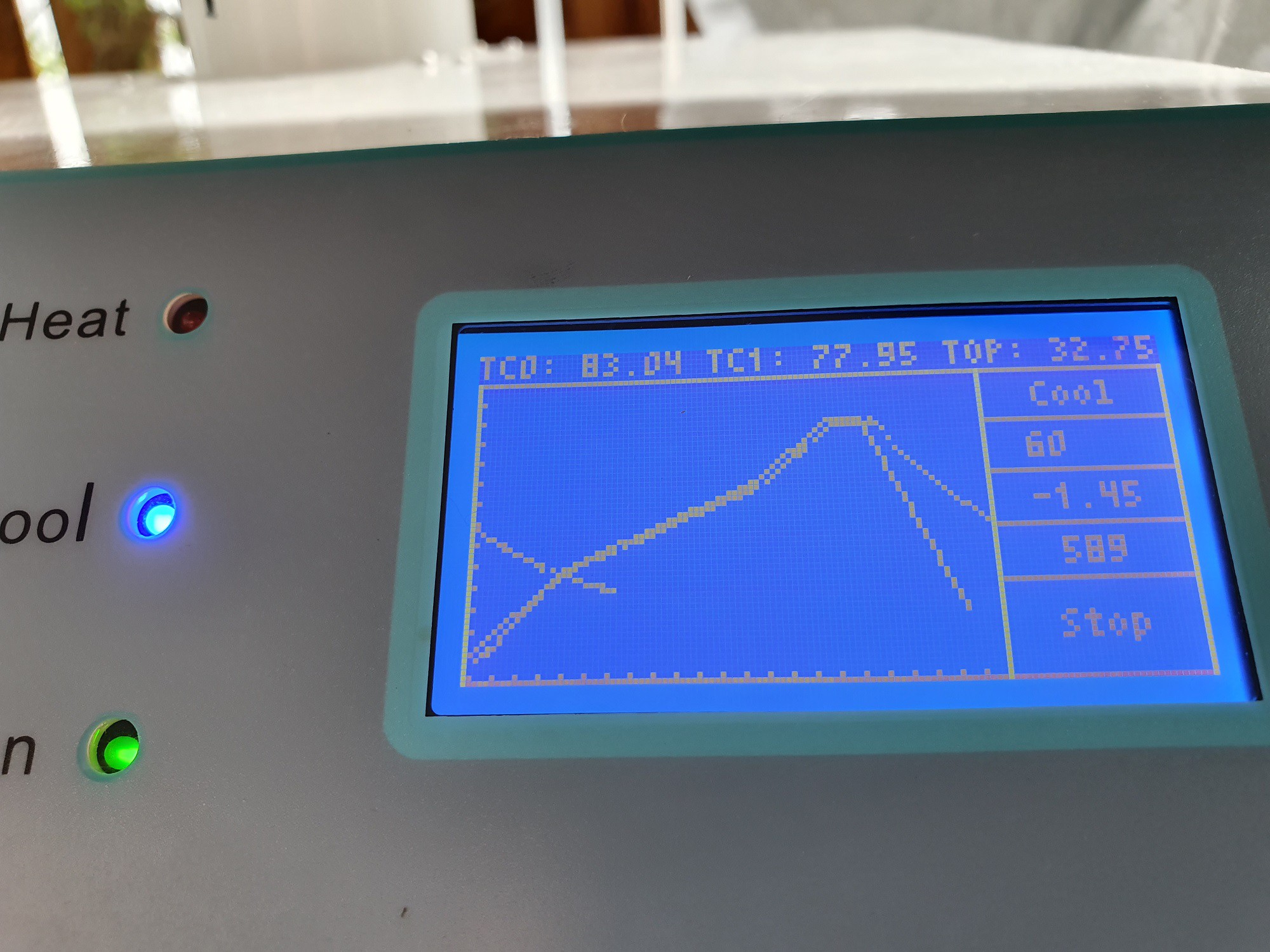
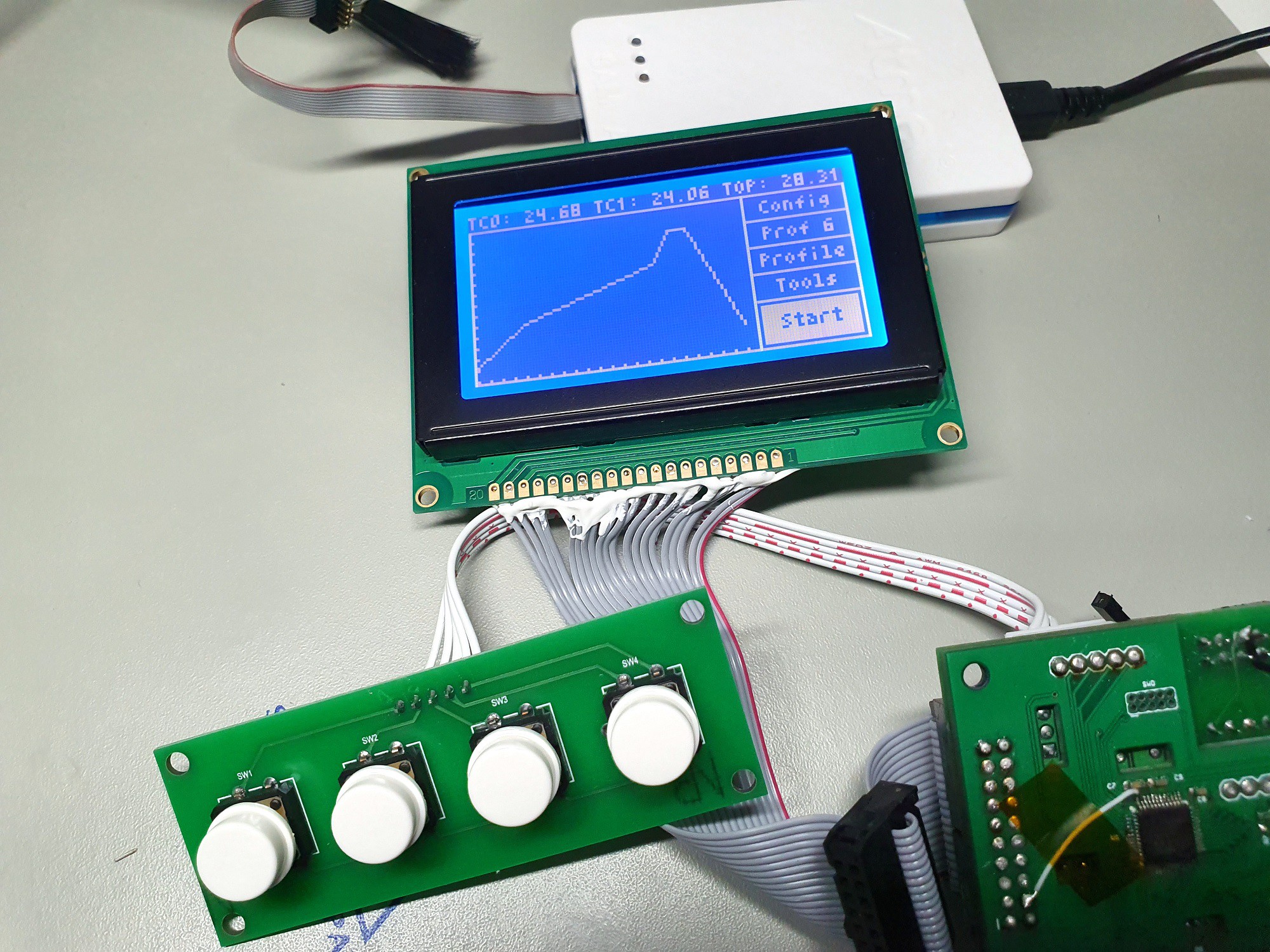
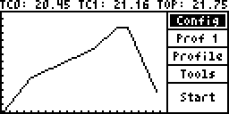 Compare this to the existing display:

 Skyhawkson
 WJCarpenter
 davedarko
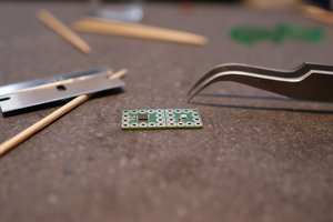
 Sina Roughani