 igorfonseca83
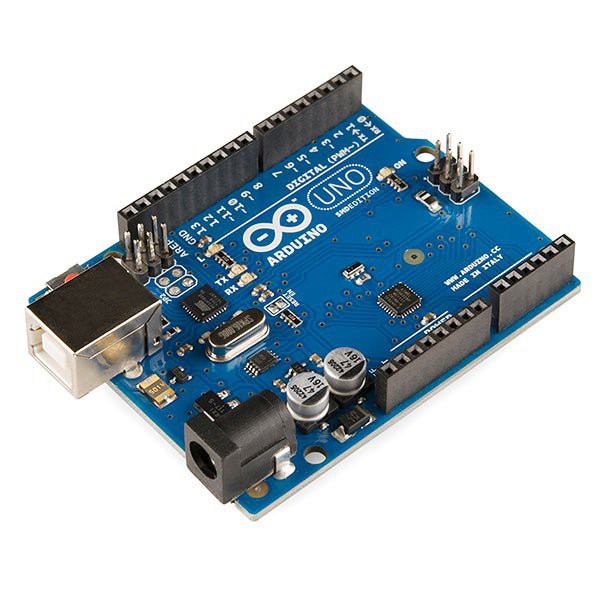
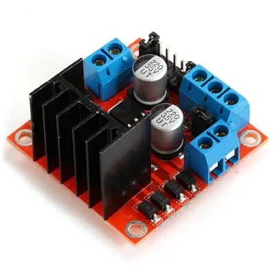
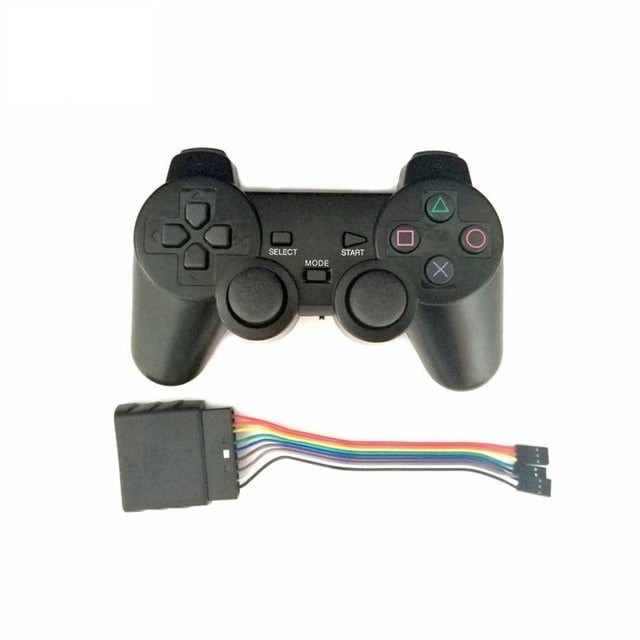
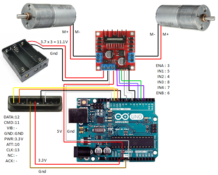
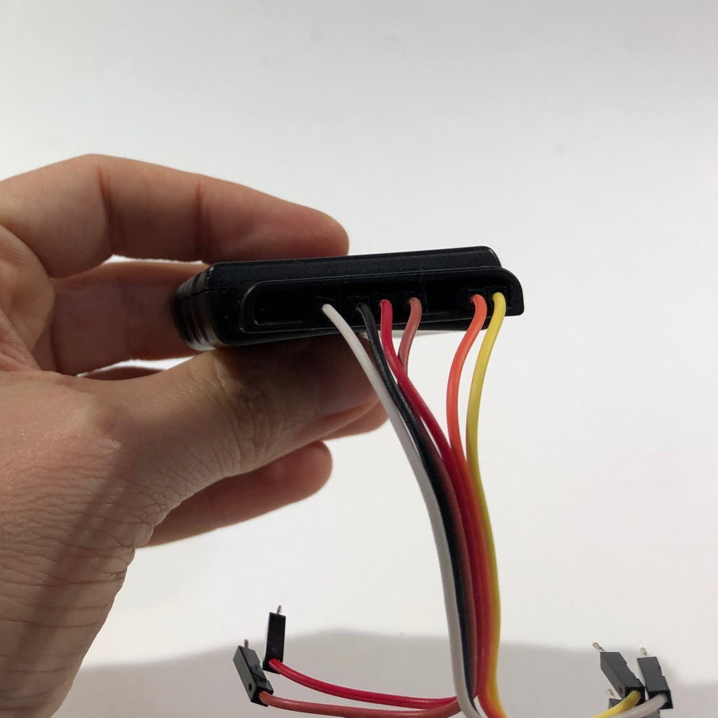
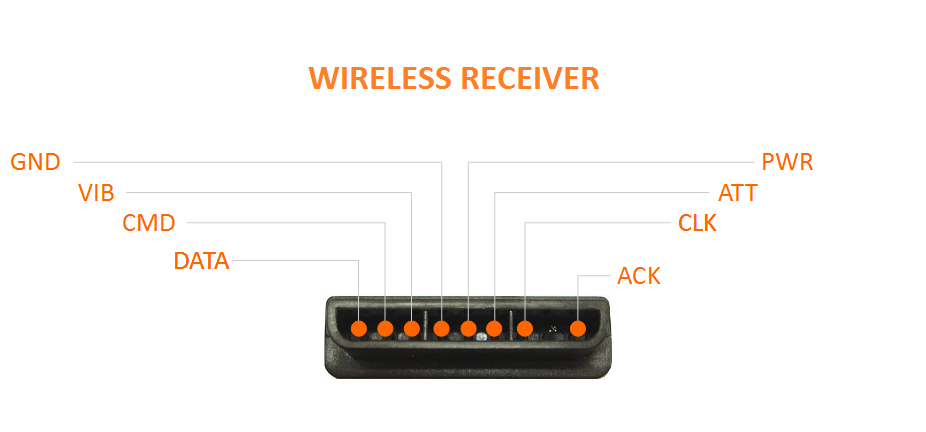
In this tutorial I'll show you how to use a wireless Playstation 2 (PS2) joystick to pilot a robotic tank. An Arduino Uno board was used at the core of this project. It receives commands from the wireless controller and sets the speed of the motors. Other development boards might also be used (NodeMCU, Firebeetle, etc.), and the principles presented in this tutorial can be applied on other models of robots and gadgets.
I've previously designed a Blynk controlled robotic tank. It connects to a Wi-Fi network and receives commands from Blynk server. A smartphone running Blynk app was used as a remote control, and different input methods were used: push buttons, sliding bars and even smartphone's accelerometer. You can find more about this project here: https://www.instructables.com/id/Wi-Fi-Controlled-Robot-Using-Wemos-D1-ESP8266-Ardu/
I've also made some experiments with voice commands. It might be usefull if you want to remotelly control a robot without using your hands, or if you want to made it accessible for someone with limited movements. One might think of a robotic voice controlled wheel chair, for instance. A DIY robotic kit was used, along with some of my favourite tools: Adafruit.io, IFTTT and Arduino IDE. Full instructions here:
https://www.instructables.com/id/Wi-Fi-Voice-Controlled-Robot-Using-Wemos-D1-ESP826/
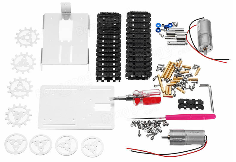
You can use different kits or even desing your own robots using simple materials, without the need of using complex tools such as 3D printers and laser cutting machines. You can find an example on one of my previous tutorials:
https://www.instructables.com/id/WiDC-Wi-Fi-Controlled-FPV-Robot-with-Arduino-ESP82/


 MrDreamBot
 Mektrasys
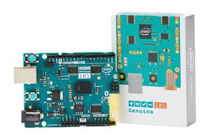
 Basanta Bhattarai
 Krunal