So, the P5 Power Glove uses 5 flex resistors to detect the flex of your fingers. I've managed to find a ribbon cable clamp that fits, so it's relatively easy to wire to it. However, it requires 5 analog pins, plus VCC and GND. So 7 pins on a controller. I'll probably hook it into an Arduino Nano, and talk to the rest of the system through I2C.
At this point, I'll probably make it modular, so I can plug the glove in separately. And while I'm at it, I'll probably add an ultrasonic range finder on the back of the hand, and a color sensor on the palm of the hand, because why not? The nano can handle all that and report back to the main module. It also means it'd only be 4 pins to the glove, instead of 7+.
Also, I can't really use a NodeMCU as the main controller - it just doesn't have the horsepower, and certainly lacks in the GPIO pins. Thus a Teensy 3.2. I/O to spare!

 This is what the setup looks like so far, without the LCD screen in place. behind the LED matrix is a Adafruit mic breakout board. I'll also be wedging a MSGEQ07 chip in back, with its associated components.
 As you can see, everything fits (so far!) One problem I'm seeing is around the USB/Nunchuck ports, the edge actually has a gap due to the chamfer I put on the case - those two walls are 1mm thick due to tolerances, rather than 2mm everywhere else. I'll have to redo that.
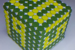
 daniel.bryand
 Mangus Tiranus
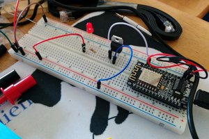
 WJCarpenter
 Craig Hissett