 Dominik Meffert
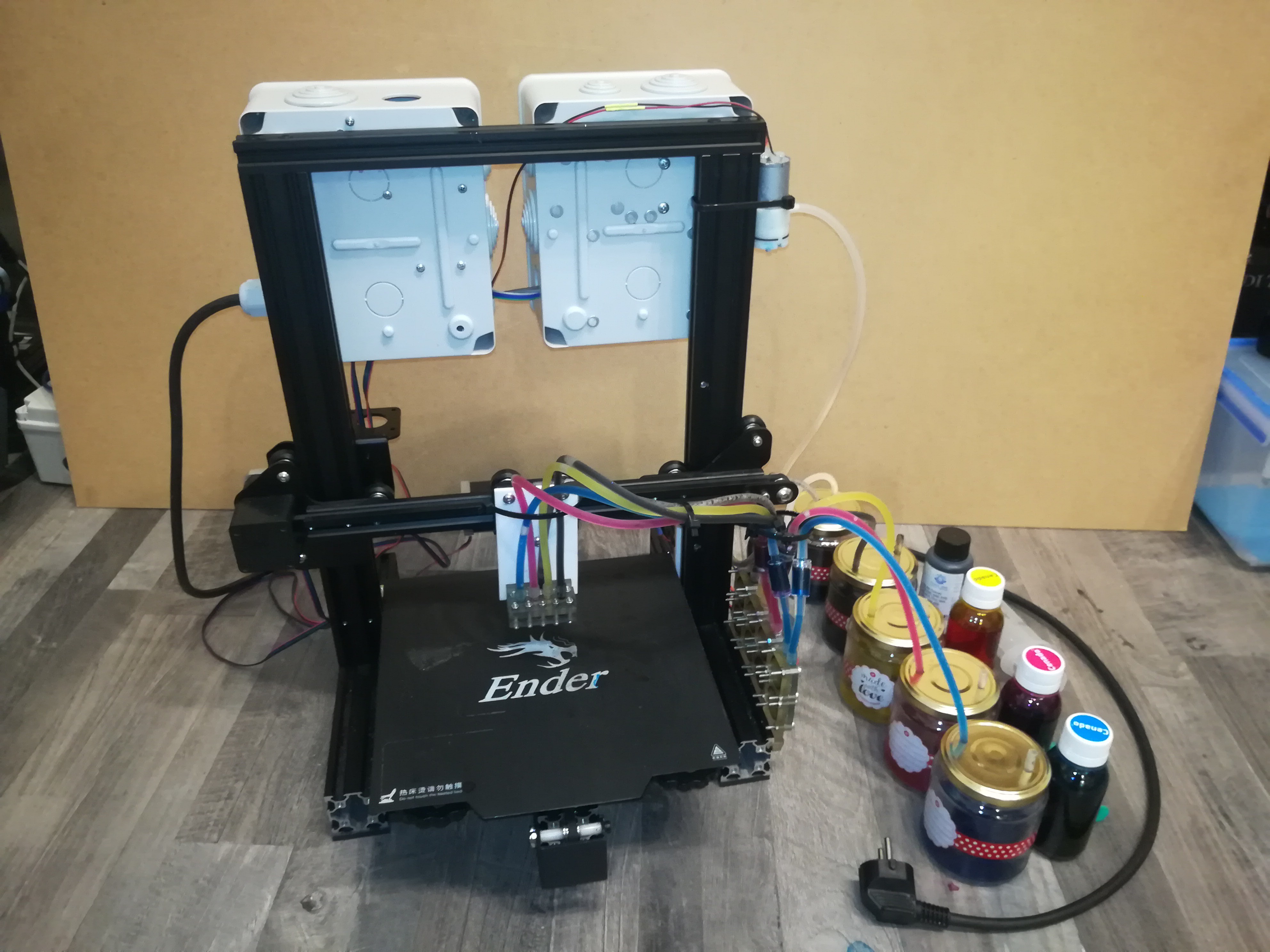
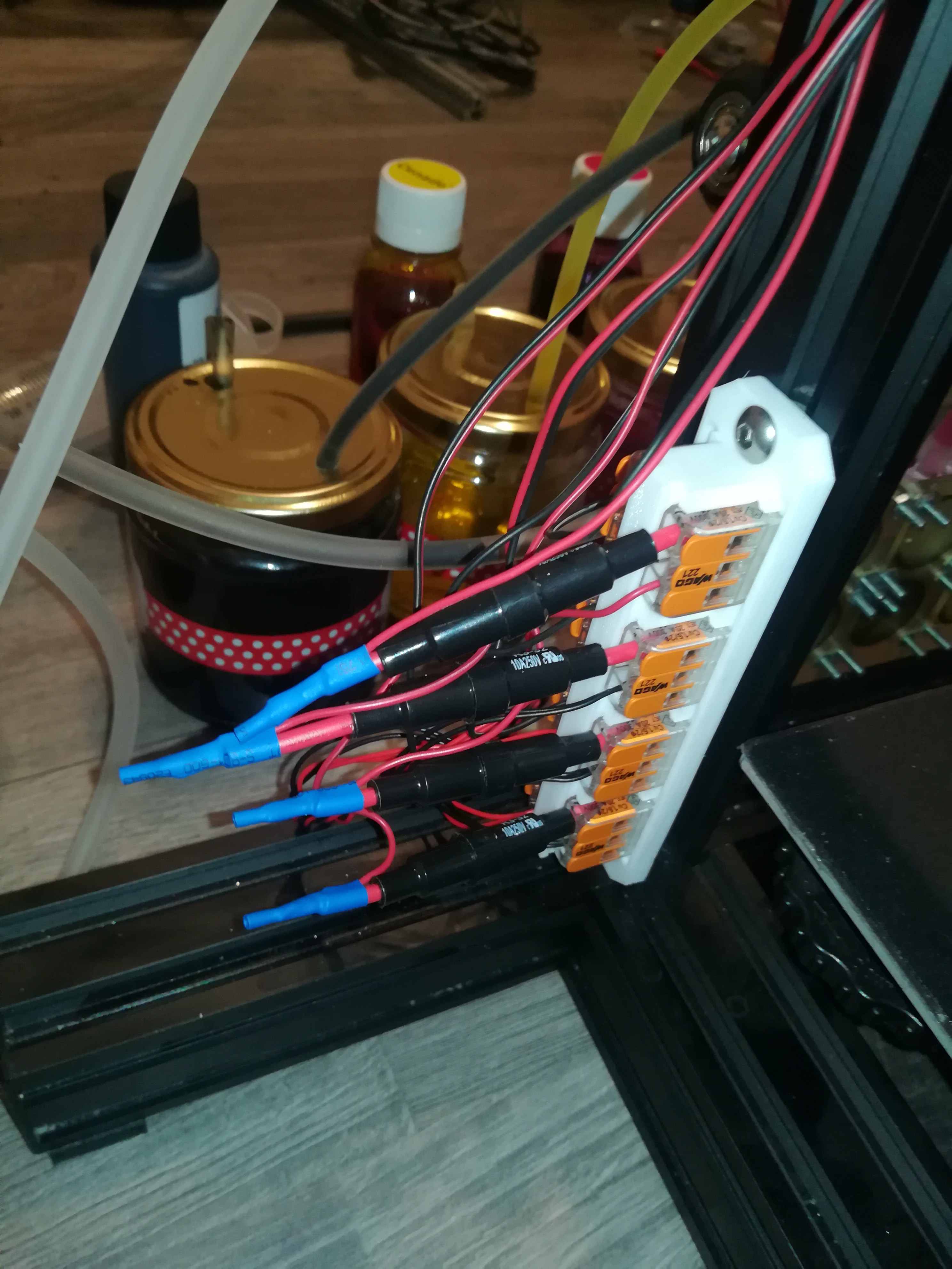
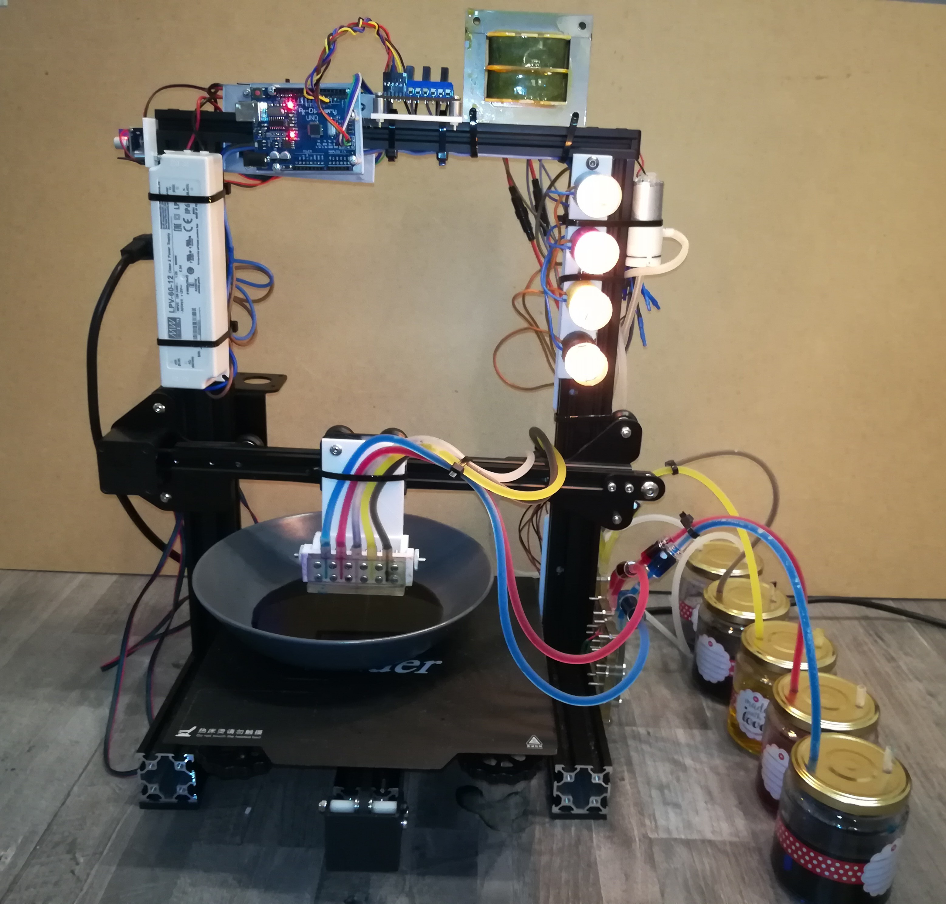
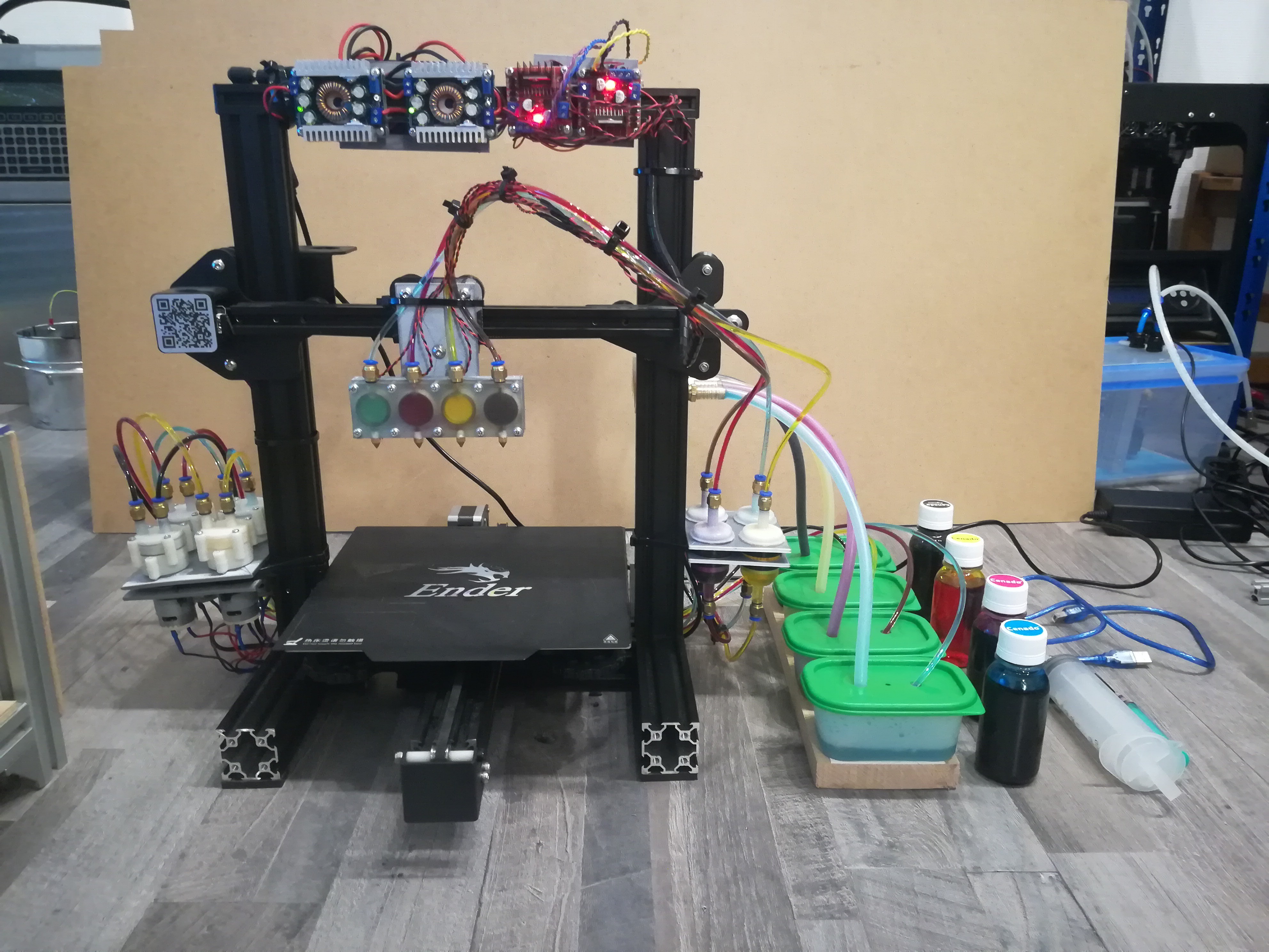
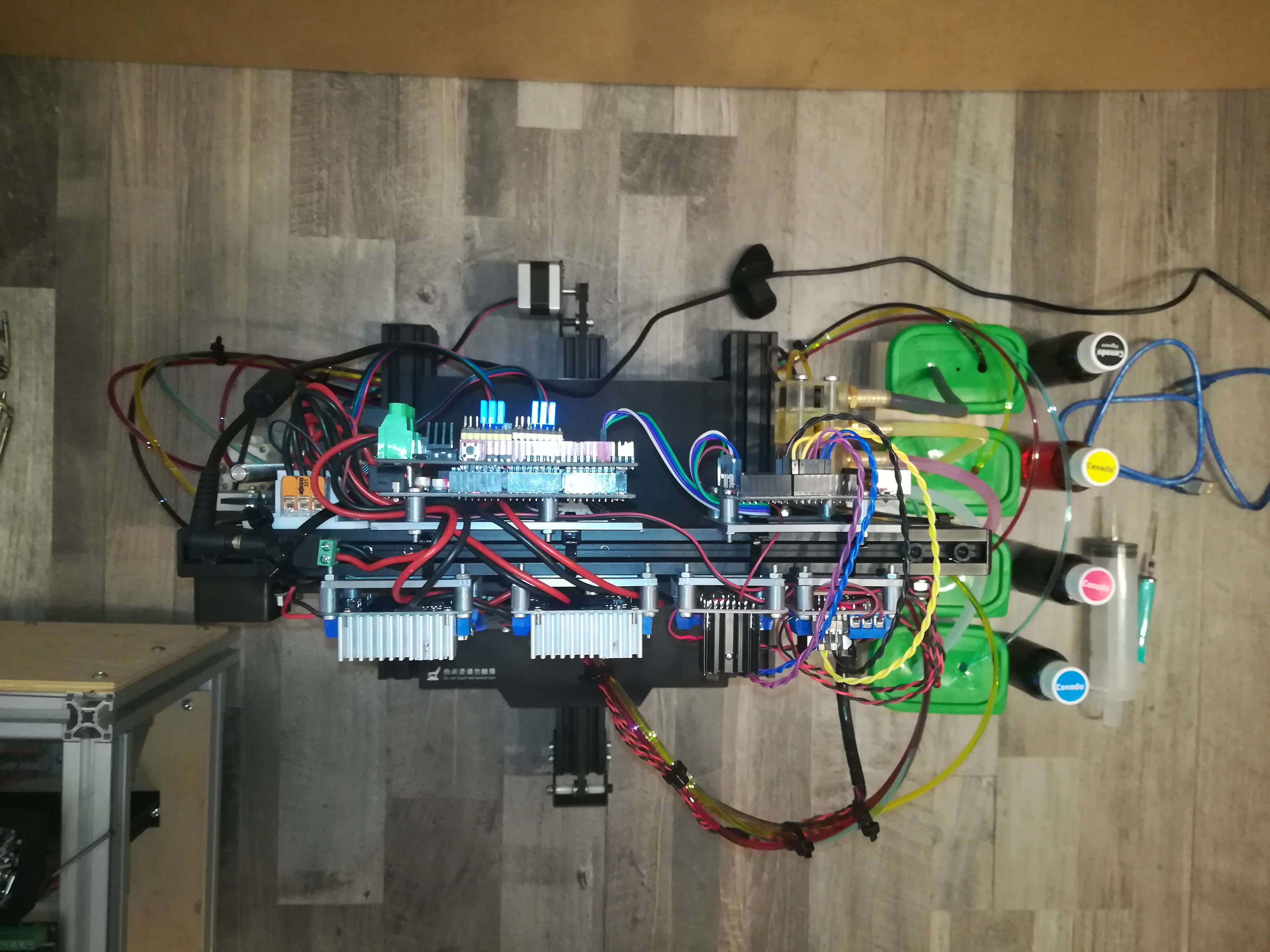
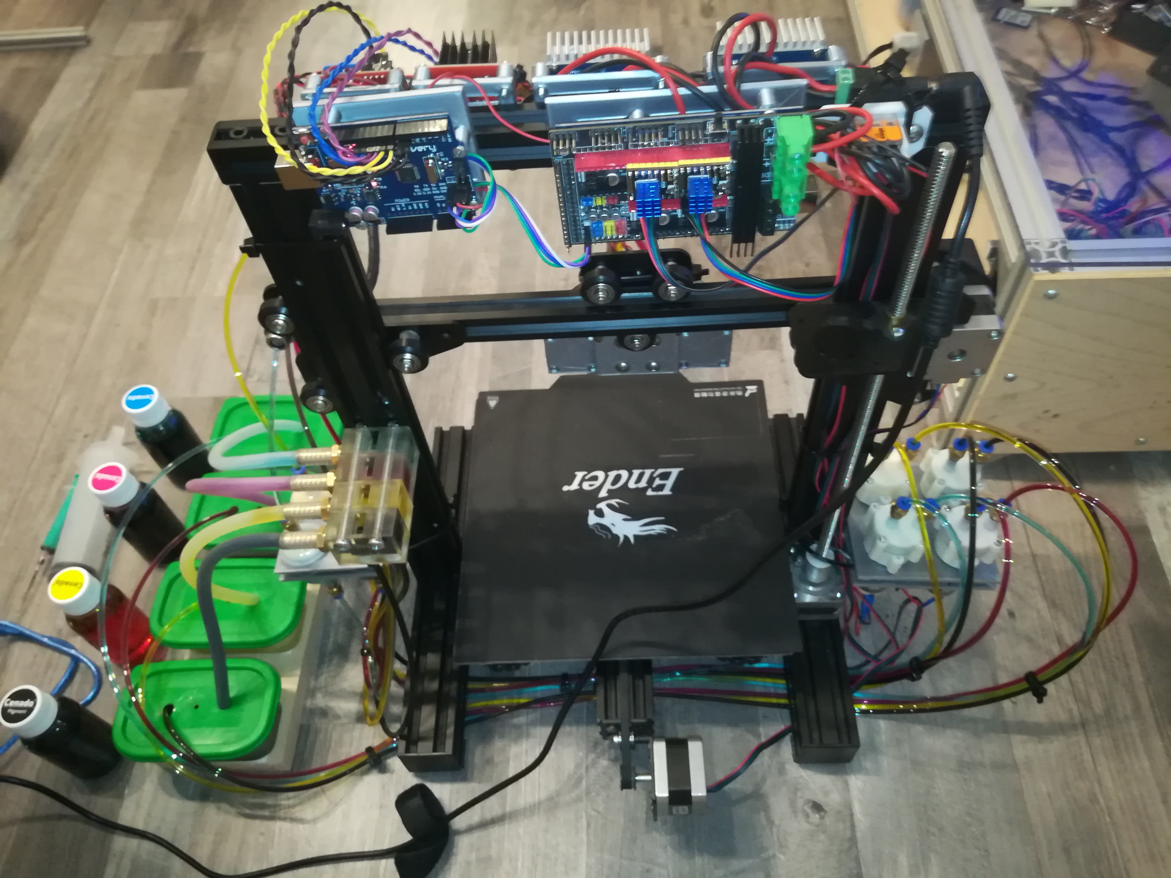
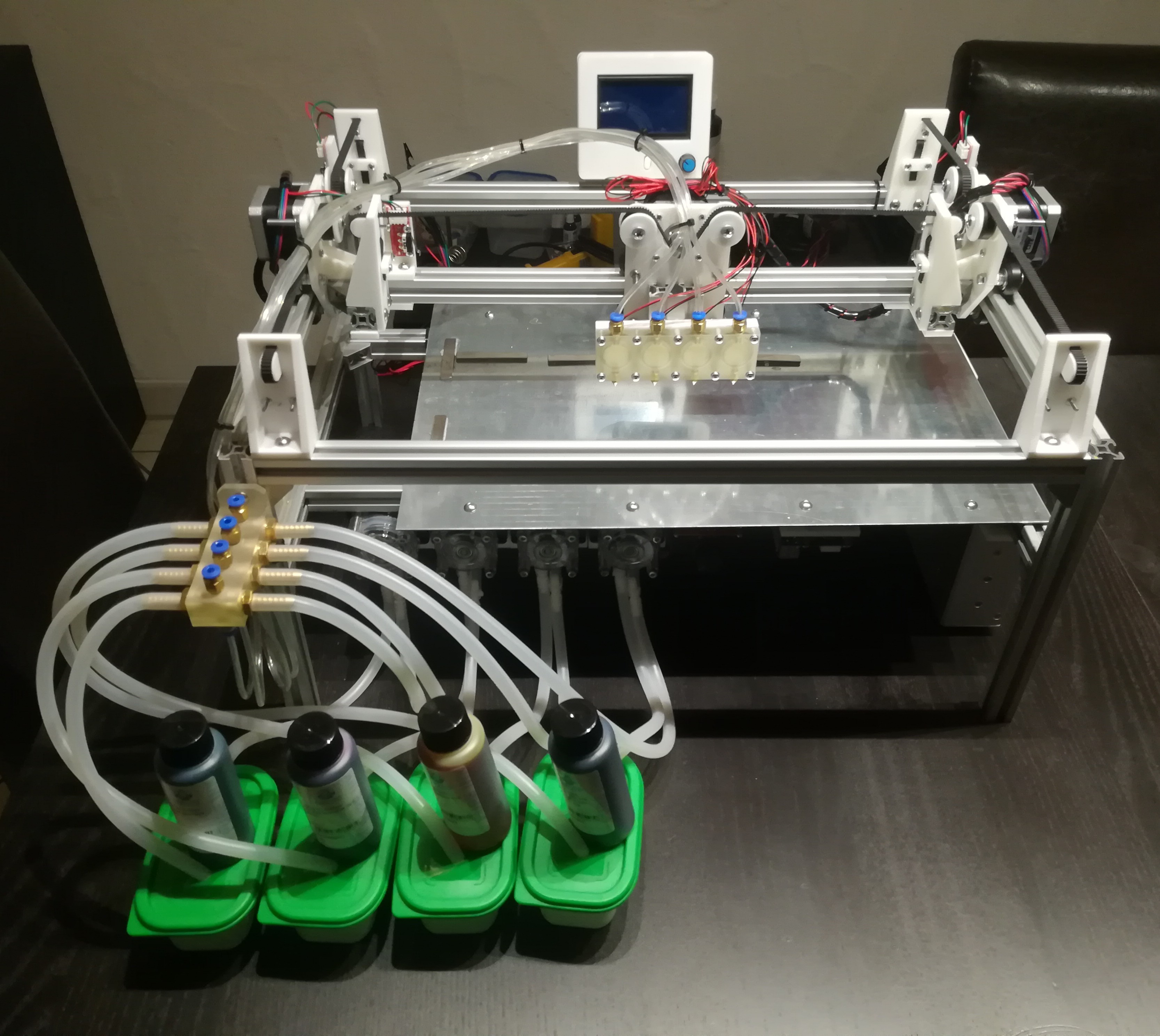
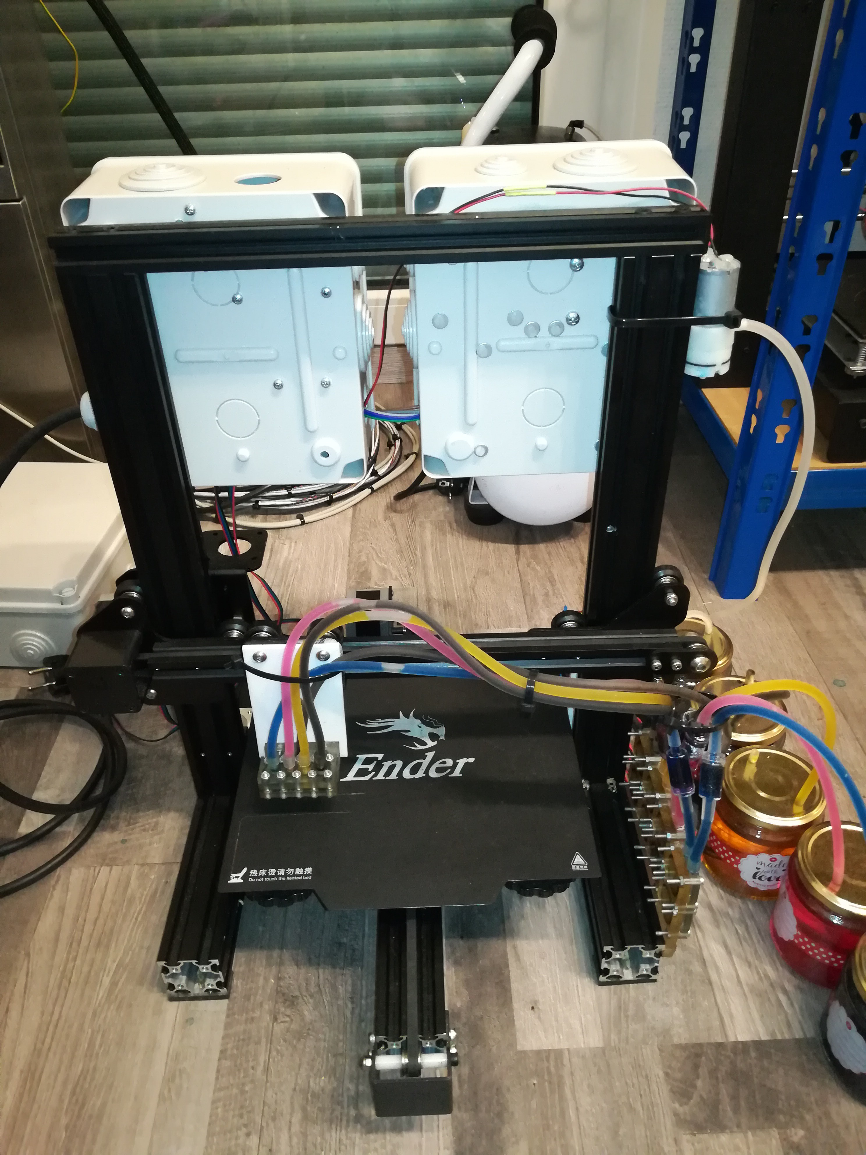
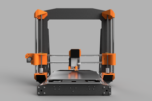
This is my attempt to build an open source inkjet printer by myself. I started this project because I wanted to build a binder jetting 3D printer but could not find any open source inkjet printer designs for this. So I started trying to build one.
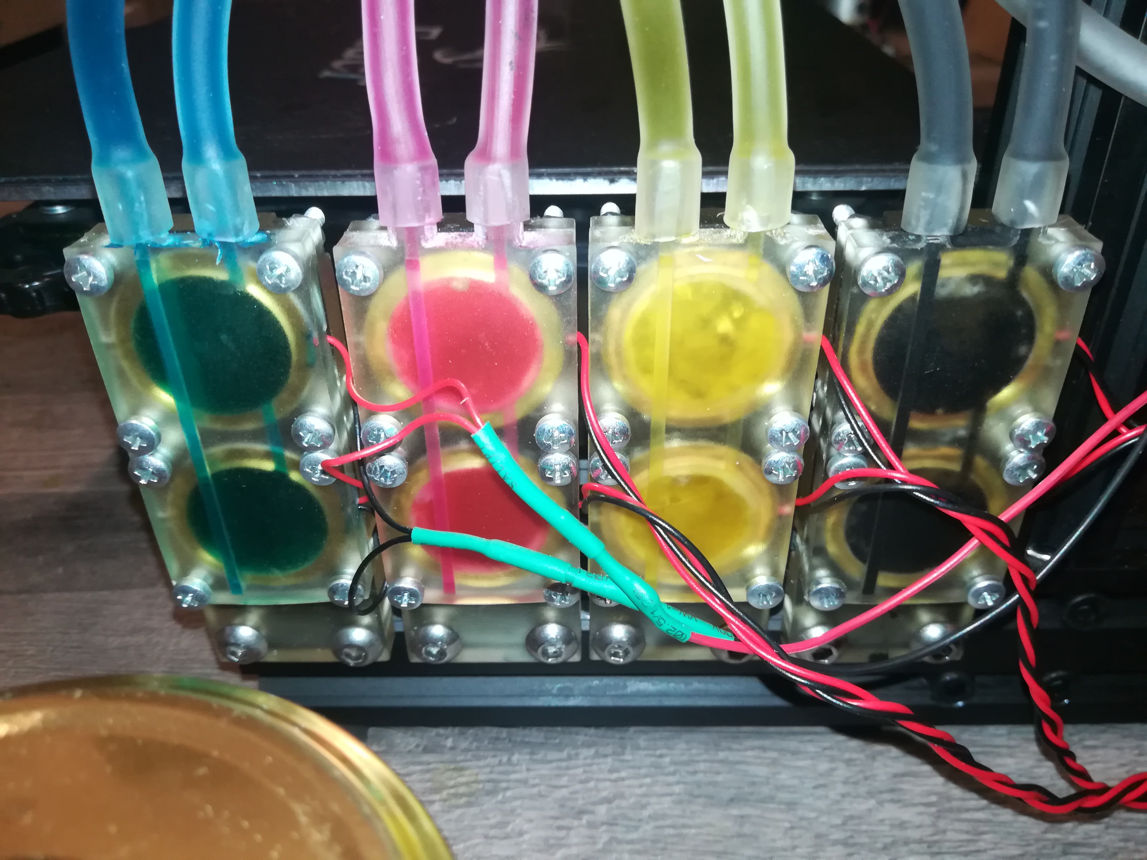
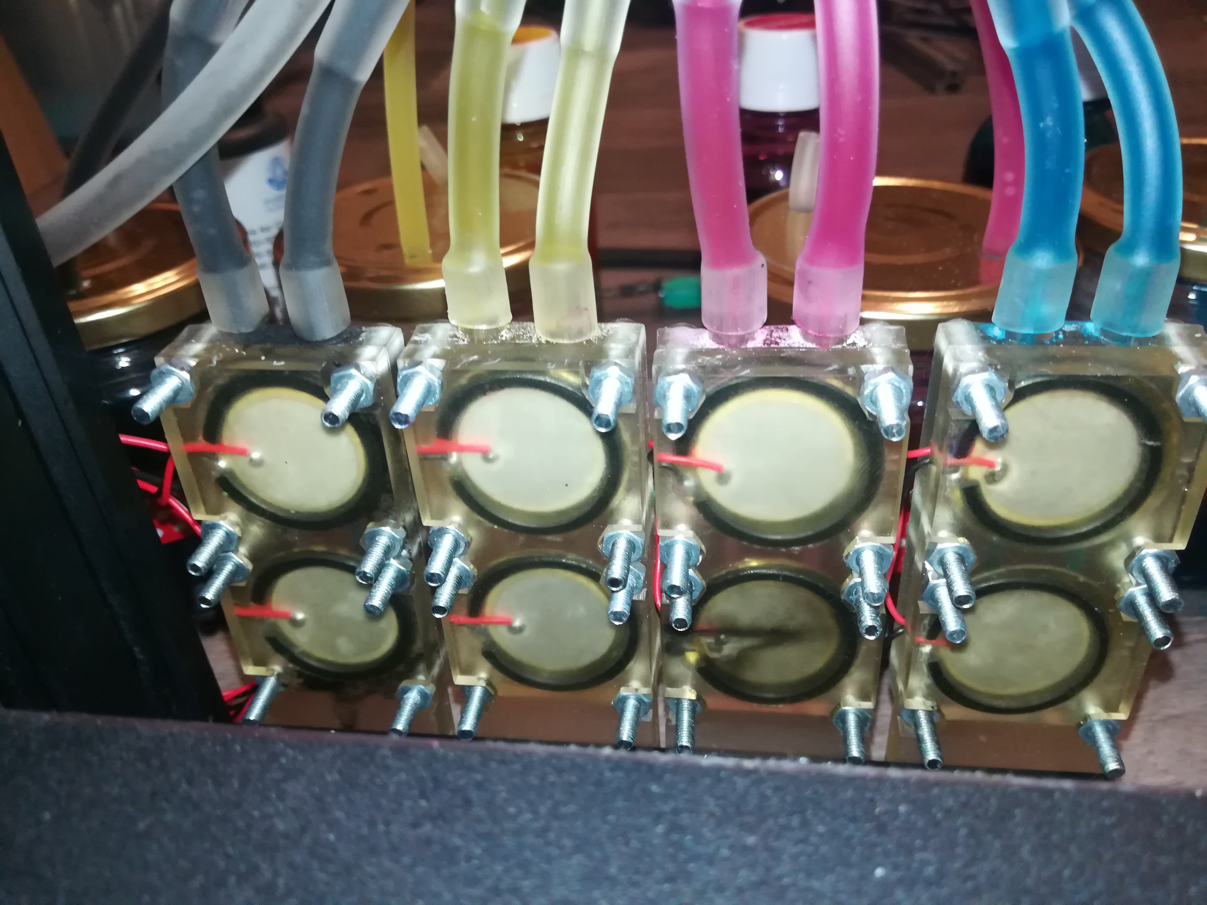
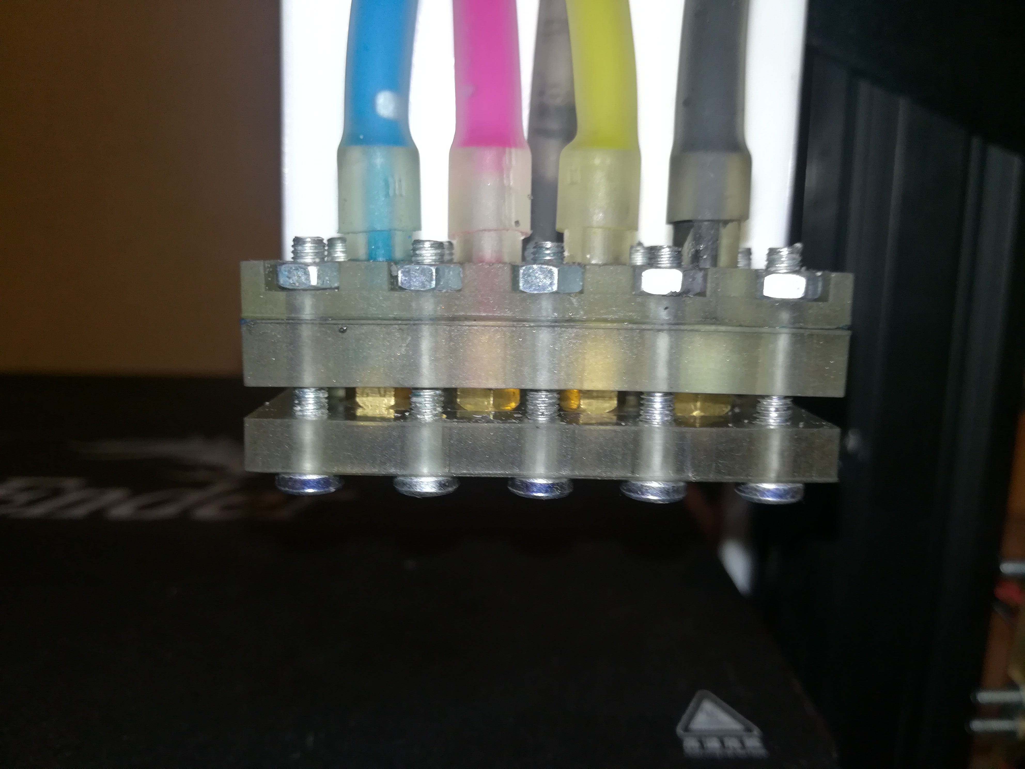
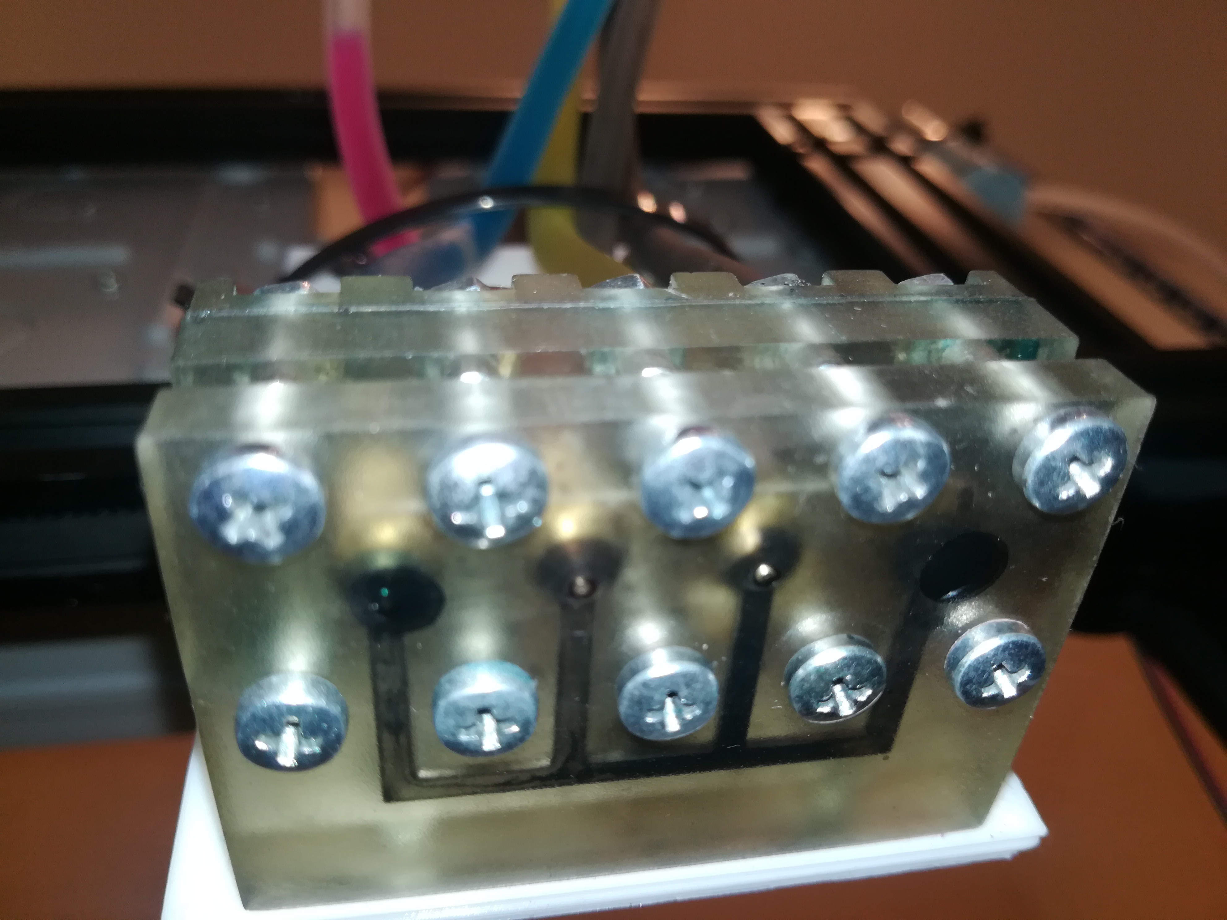
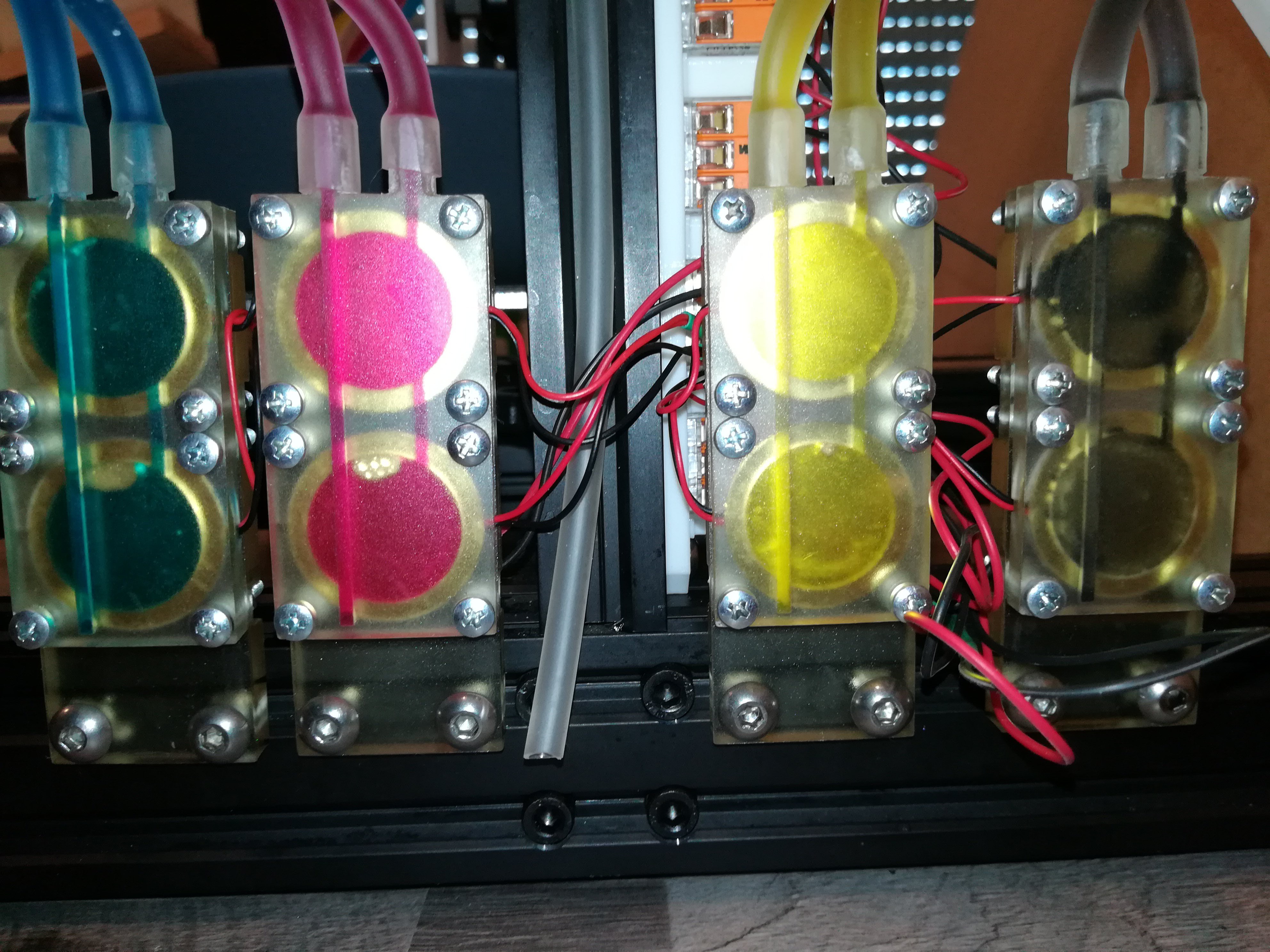
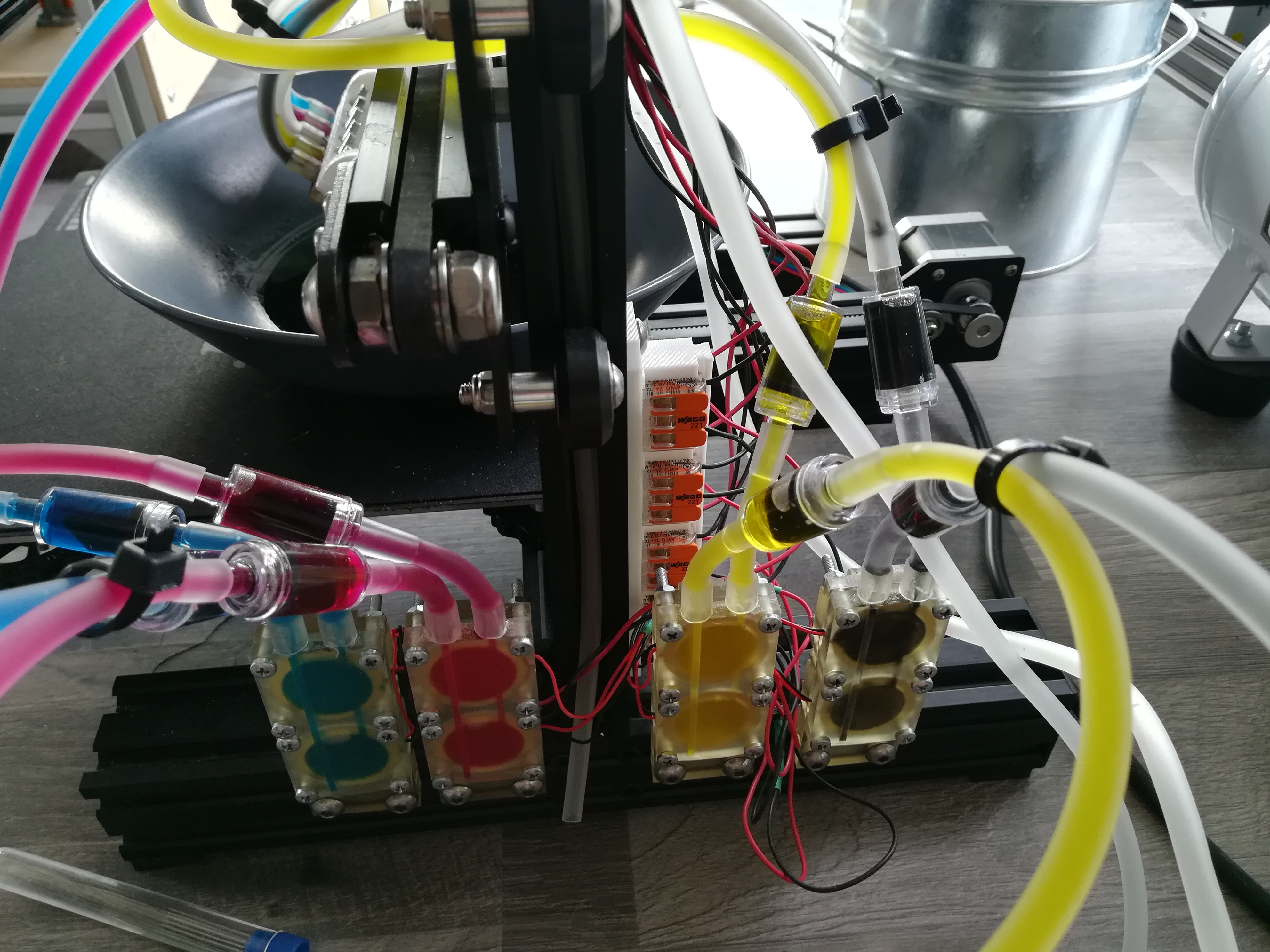
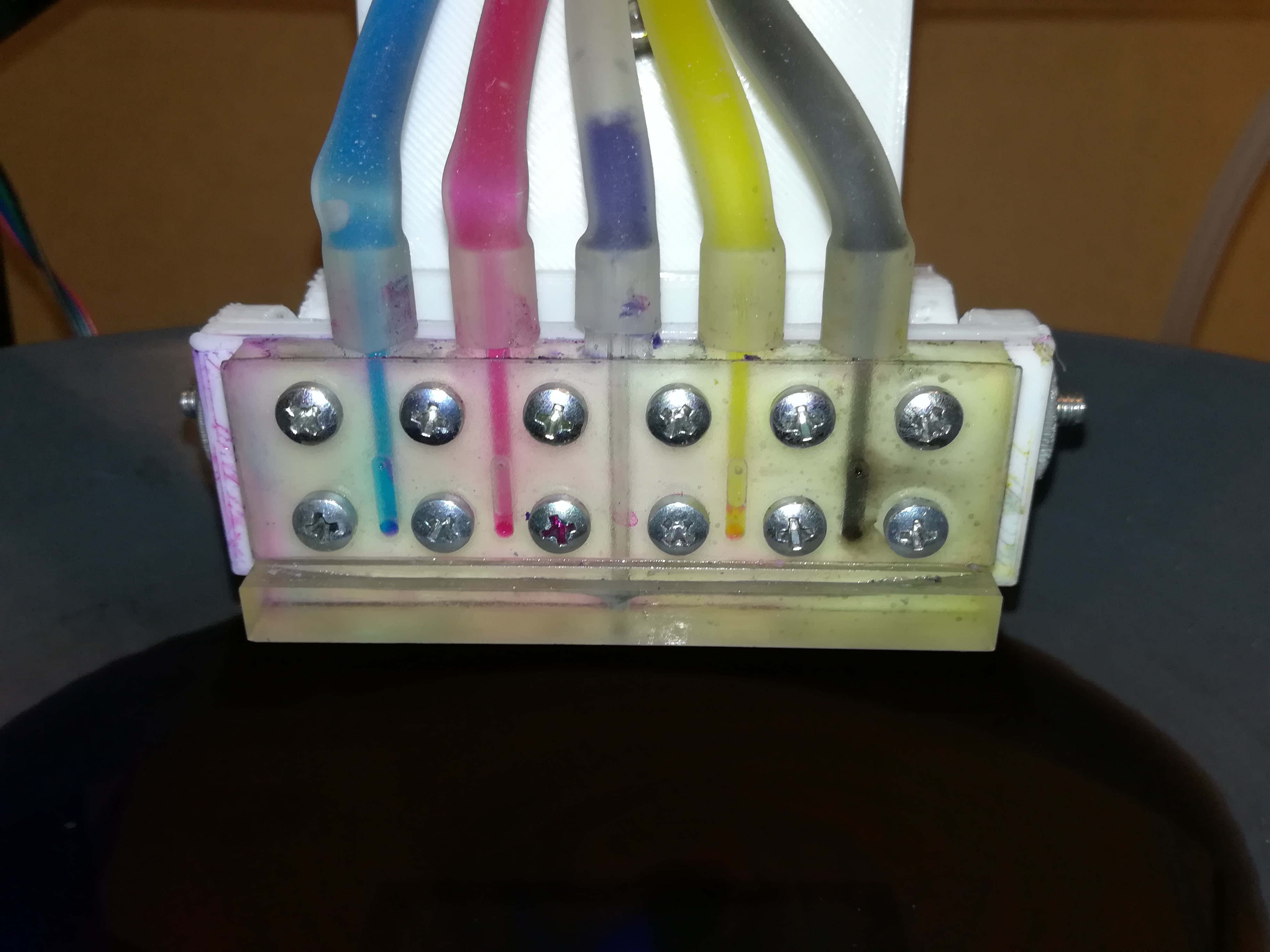
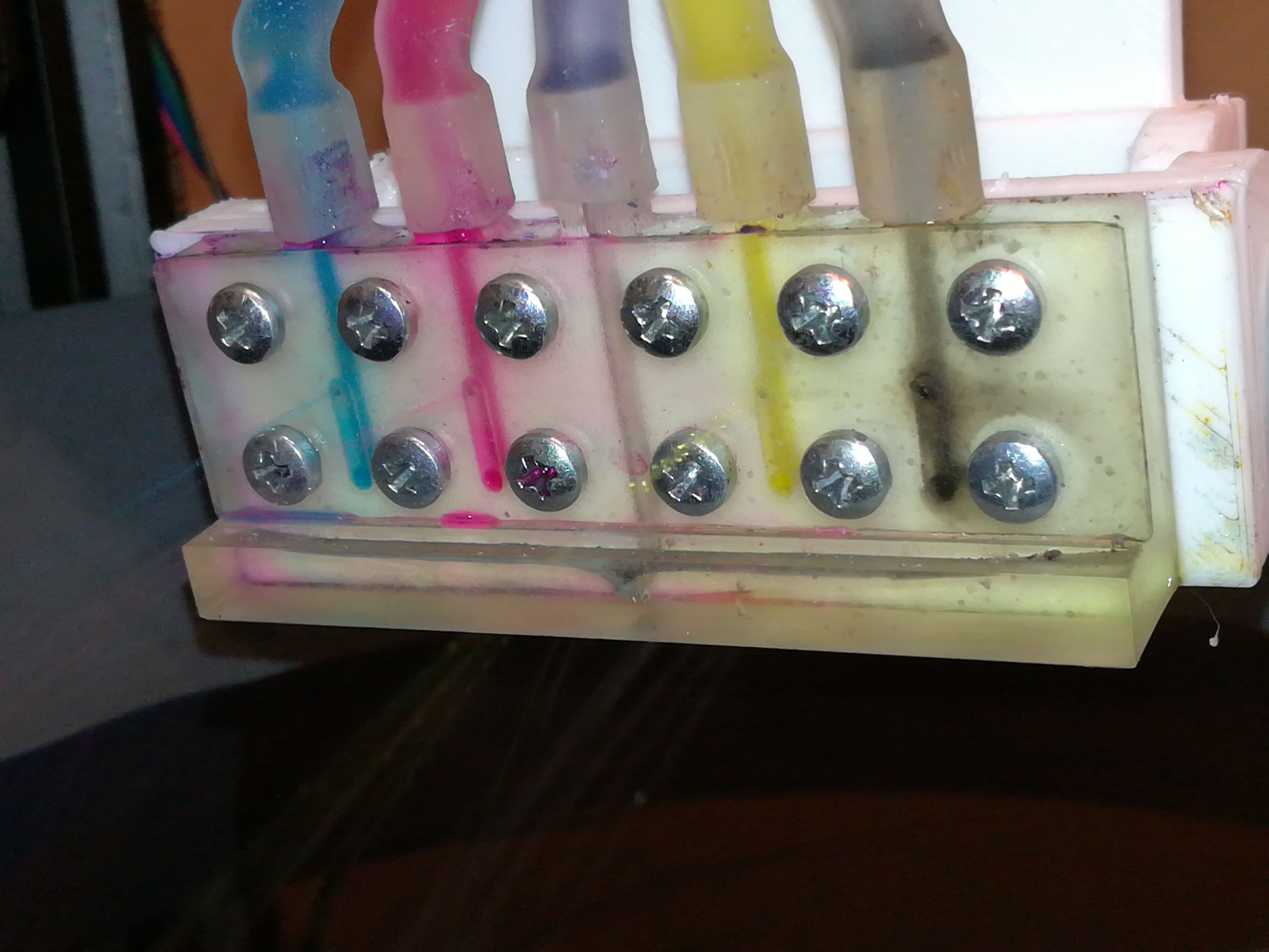
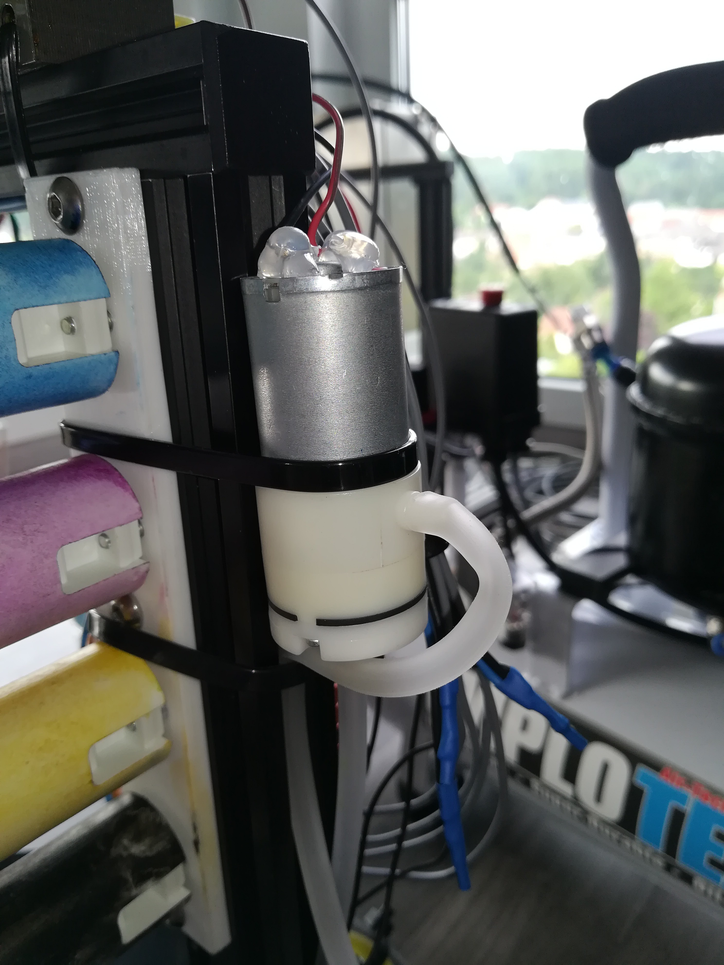
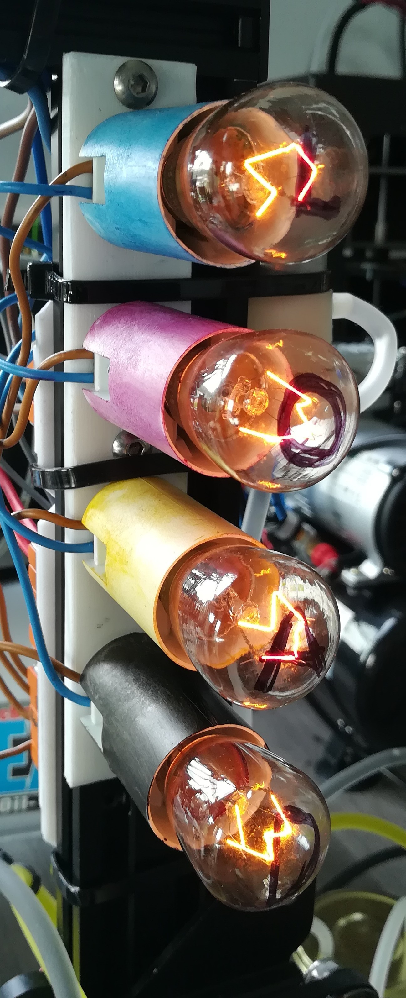
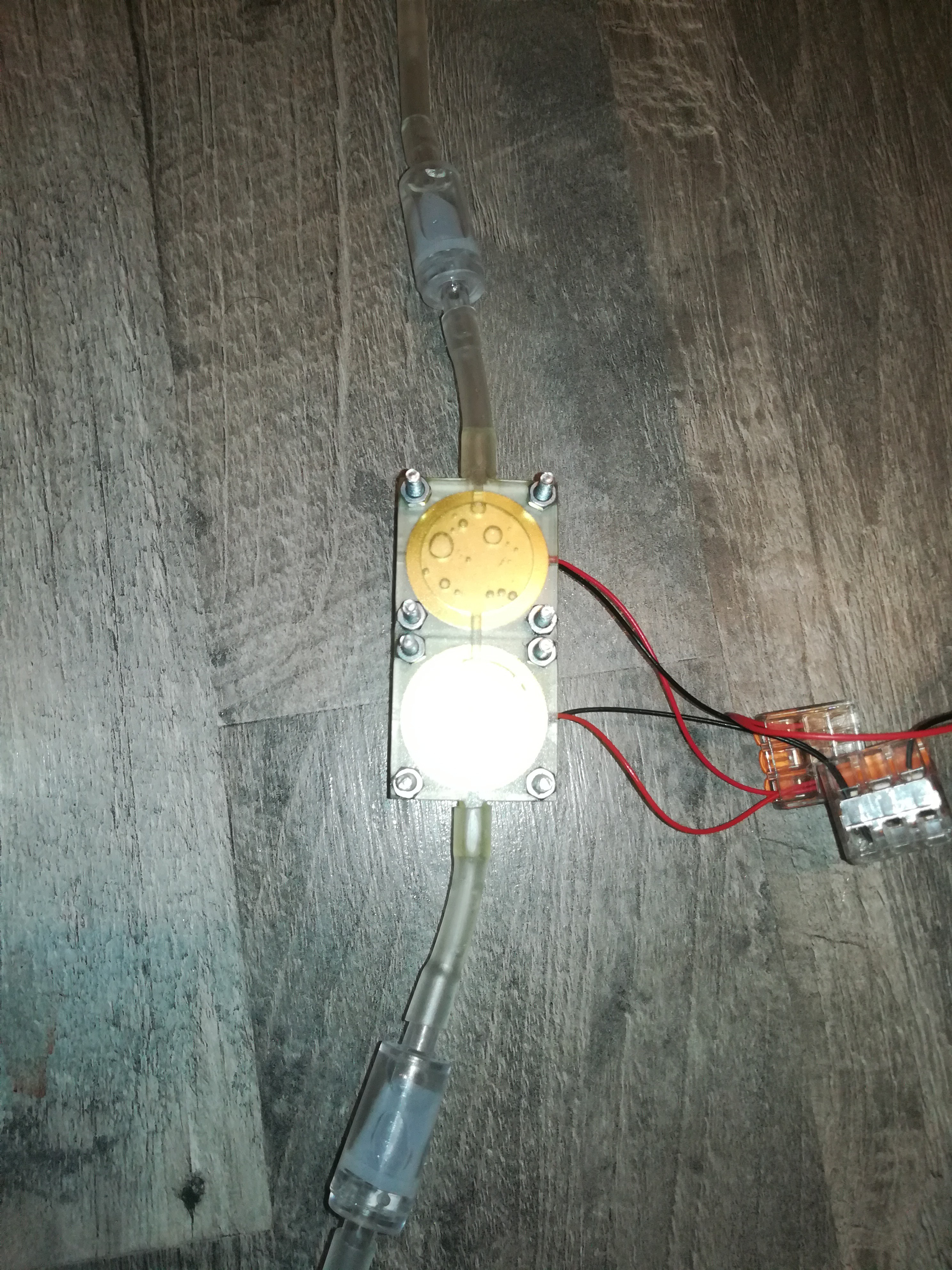
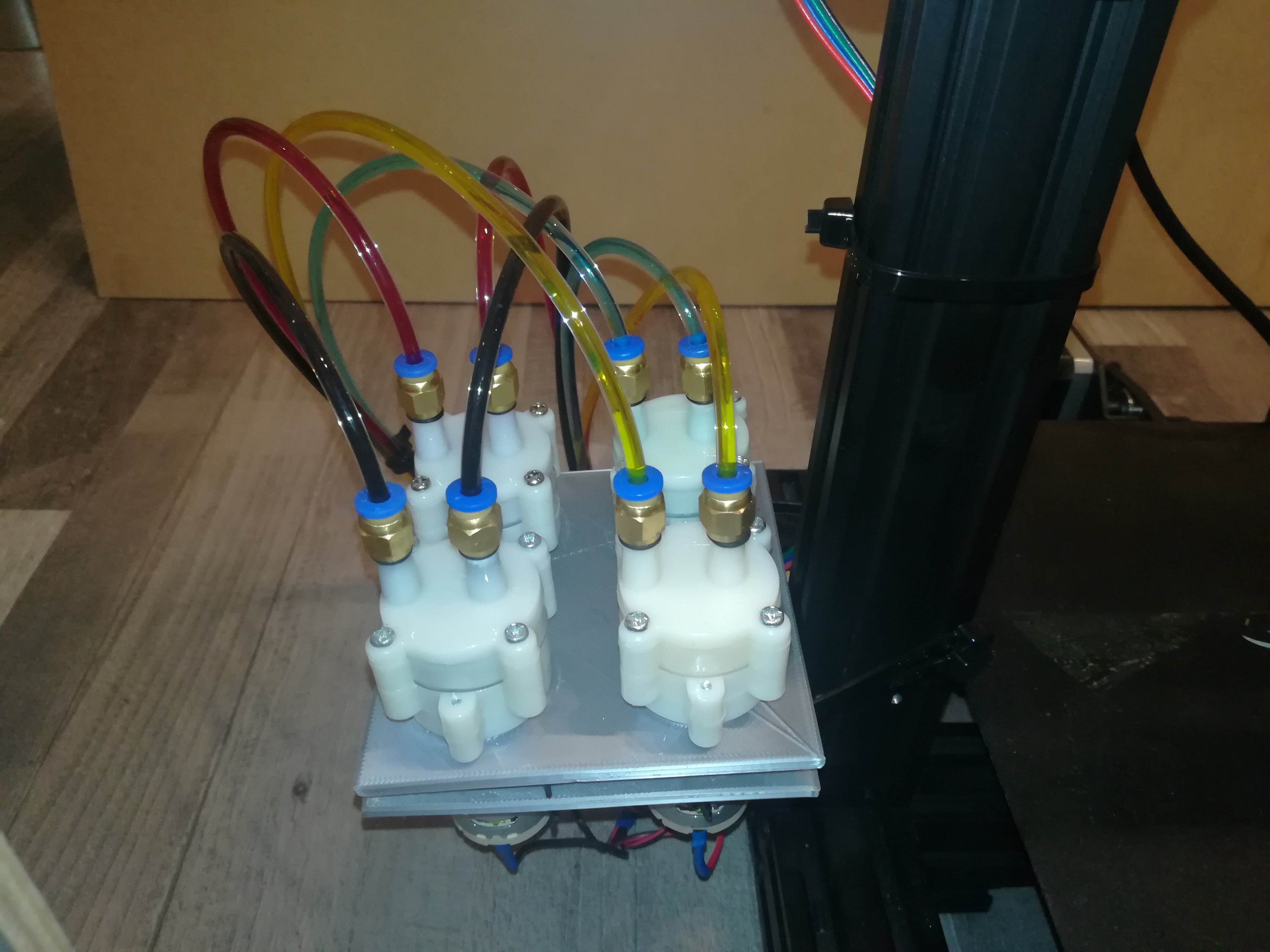
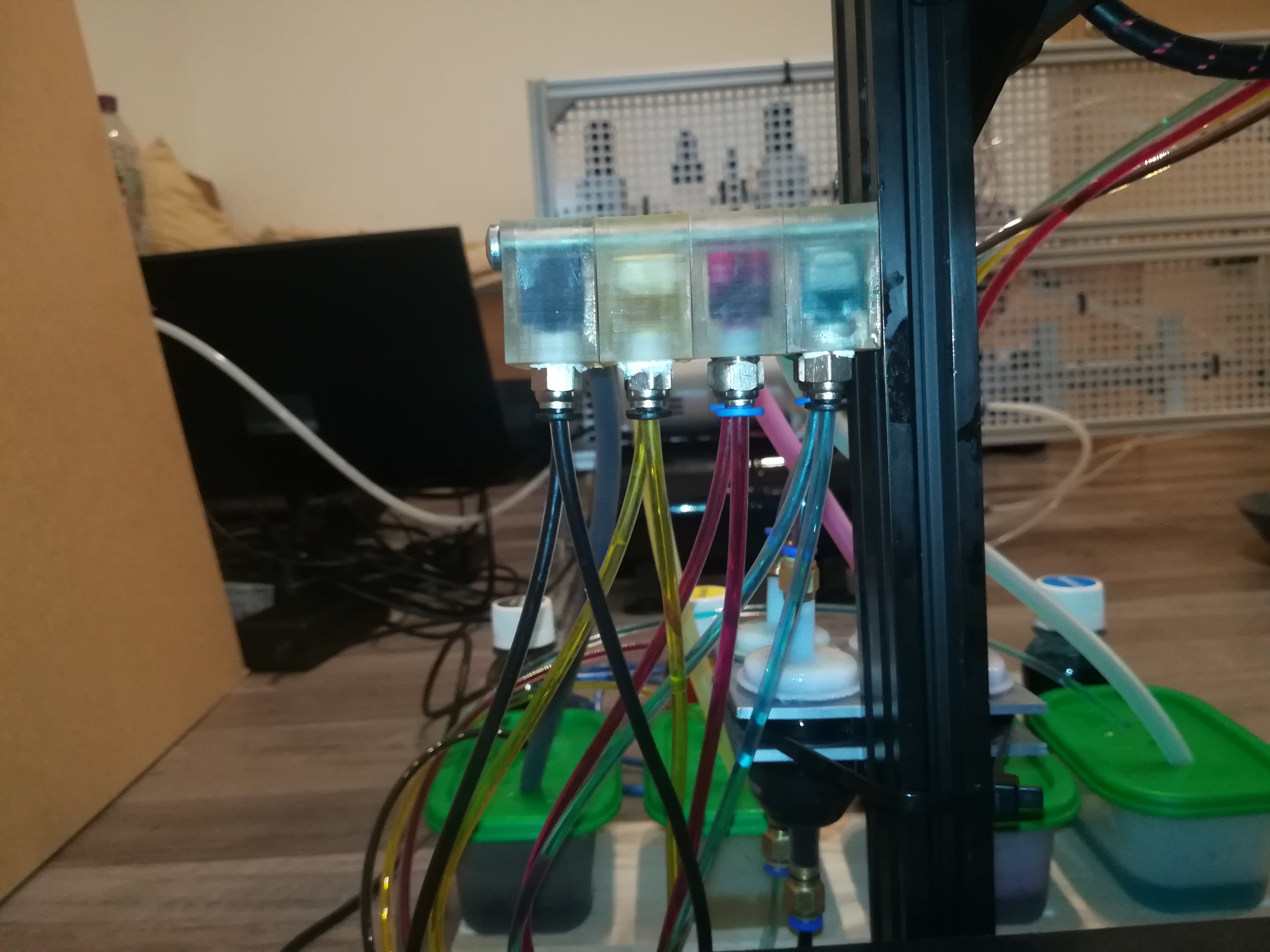
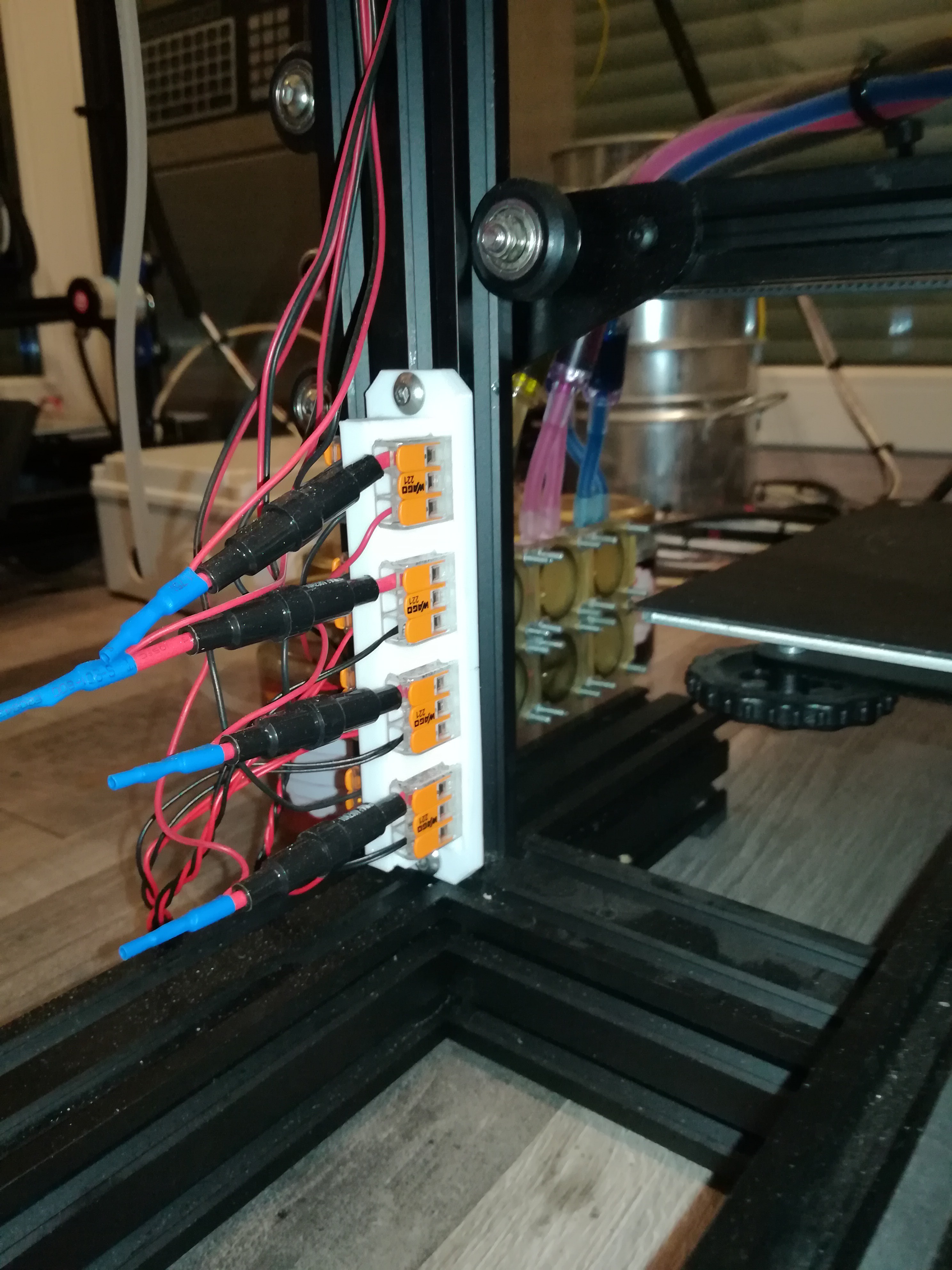
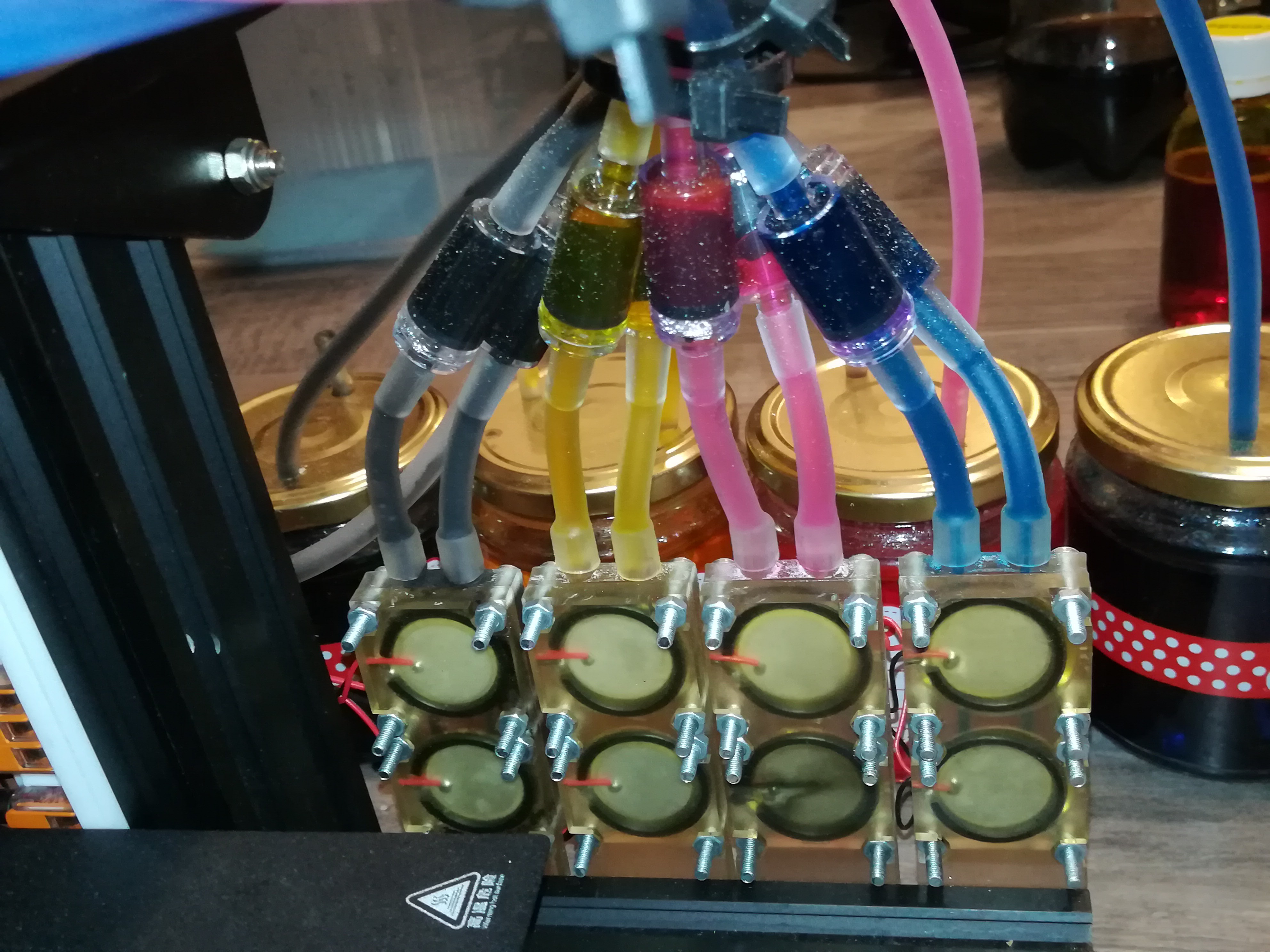
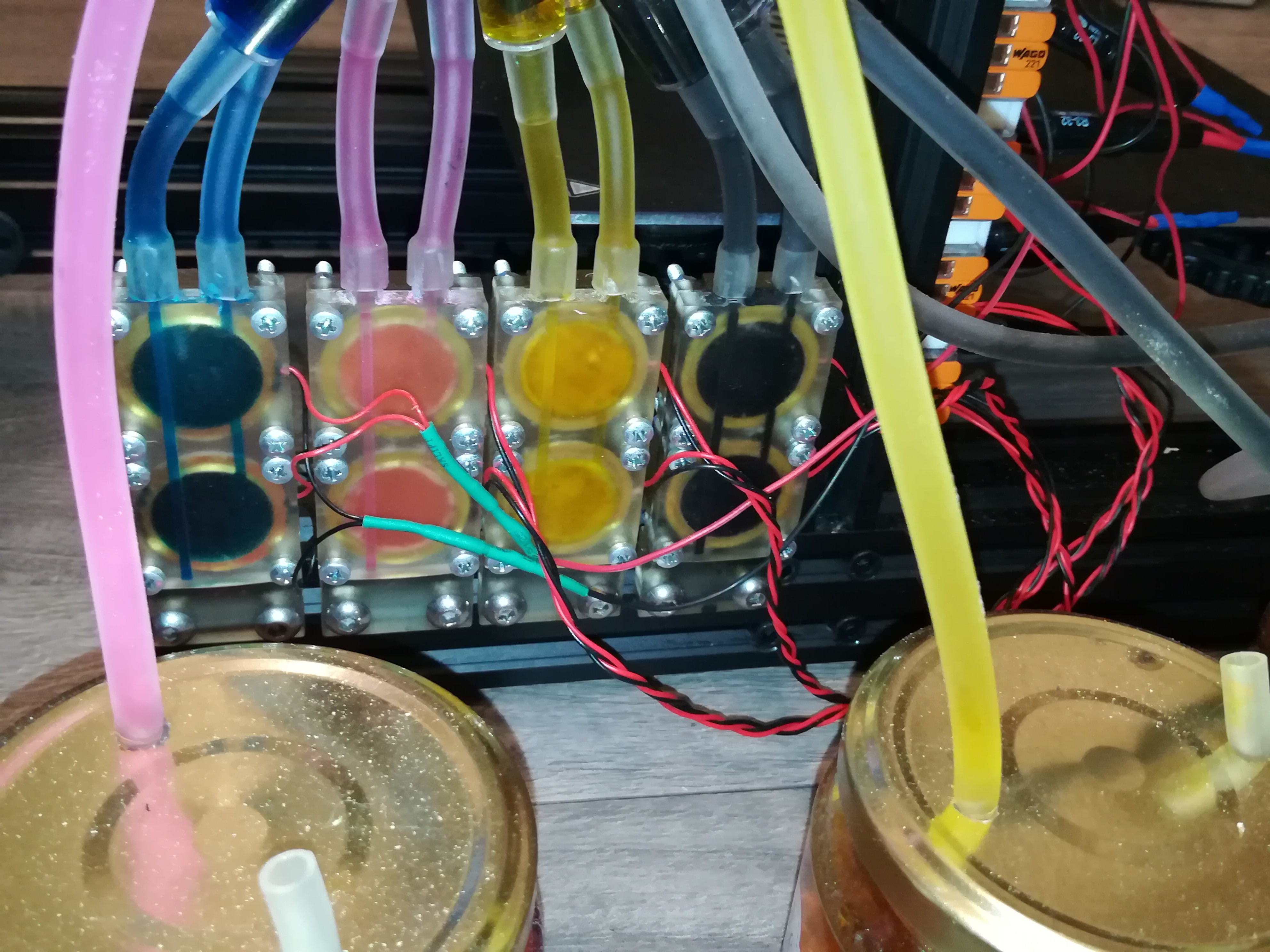
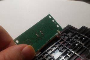
The toolhead design is a piezo printhead inspired by https://reprap.org/forum/read.php?153,52959,page=1 and https://reprap.org/wiki/Reprappable-inkjet.
Possible applications for this printer or parts of it could be:
- Single Color Printing
- Grayscale Printing
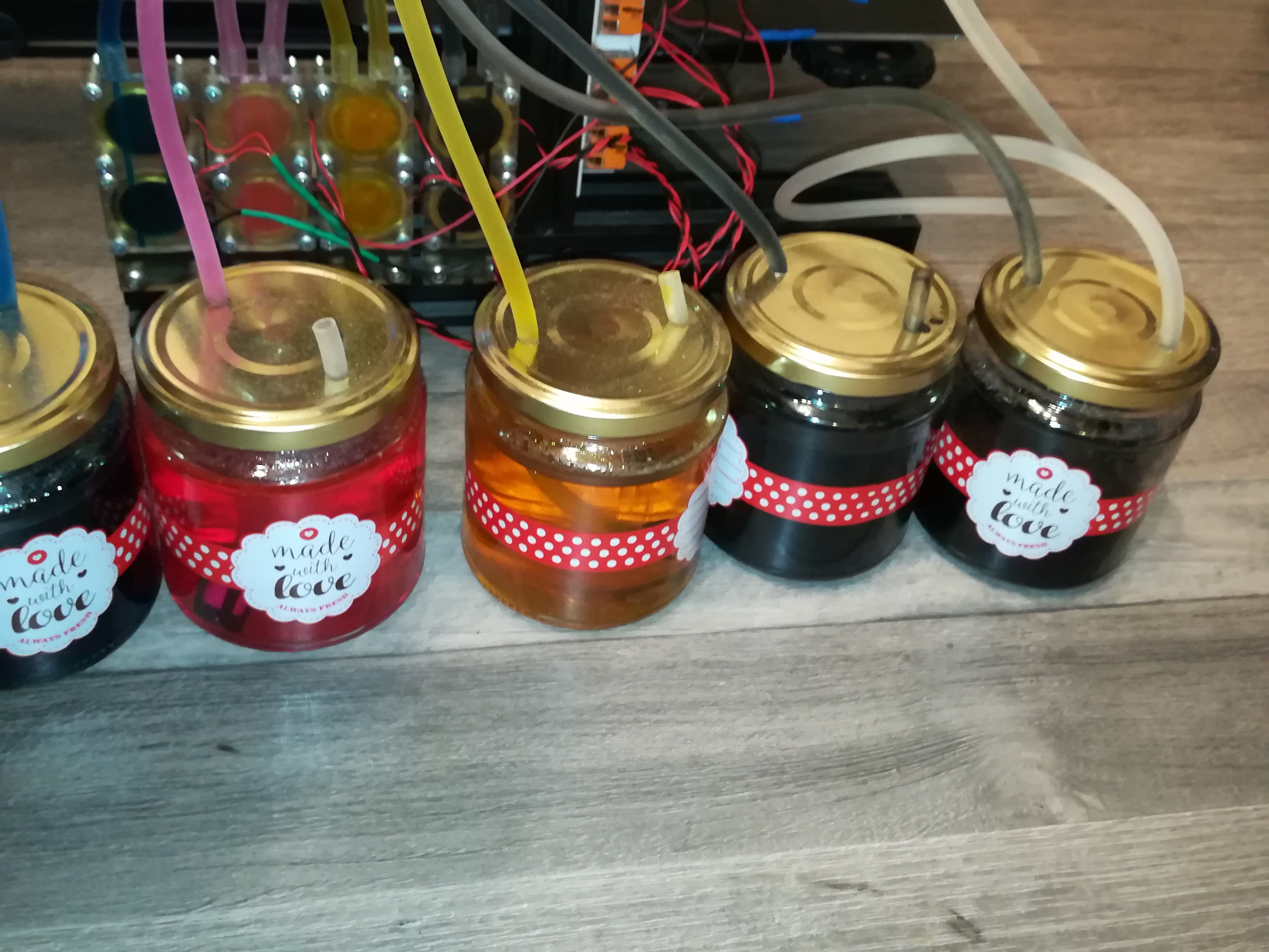
- Multicolor Printing
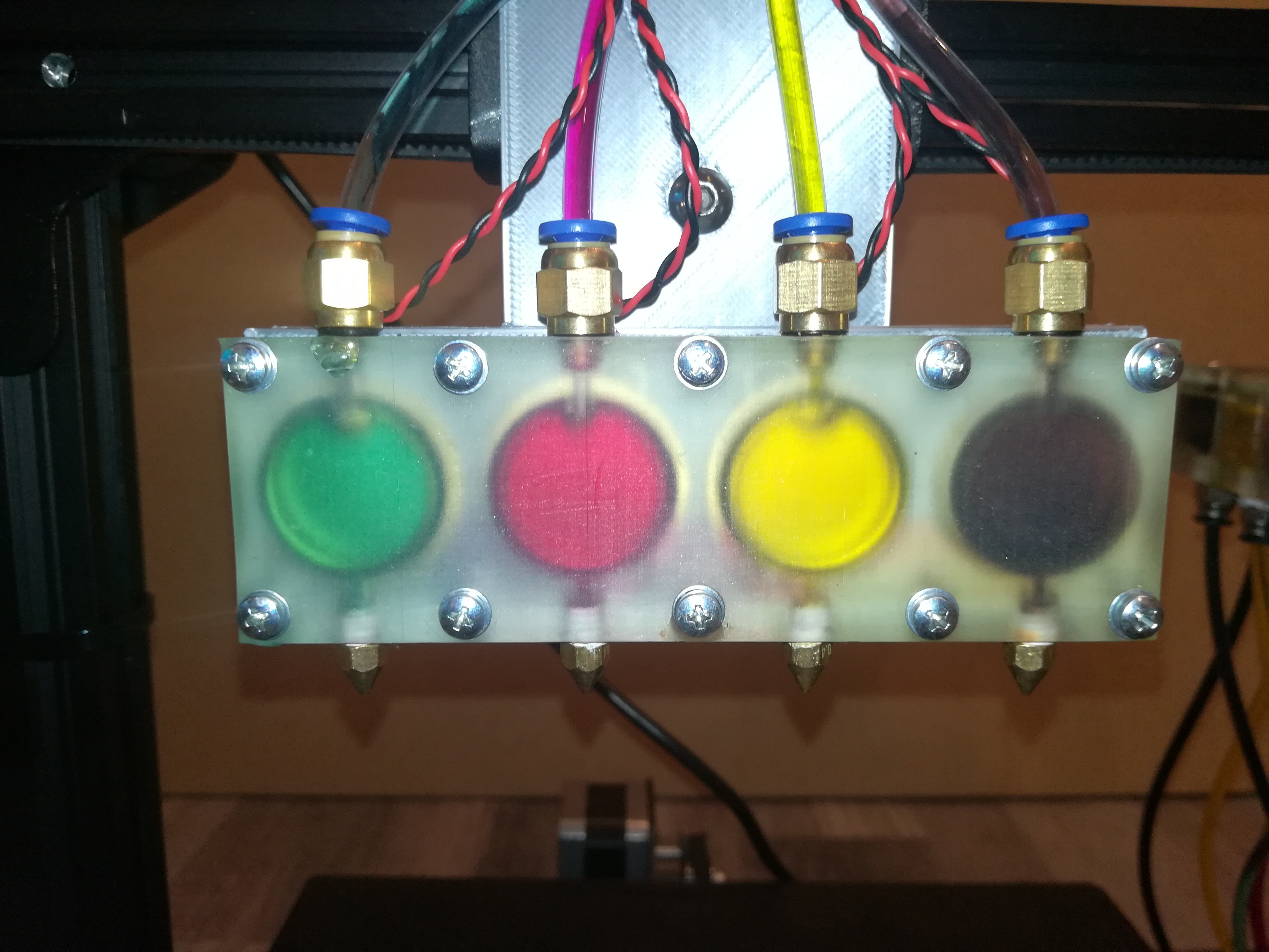
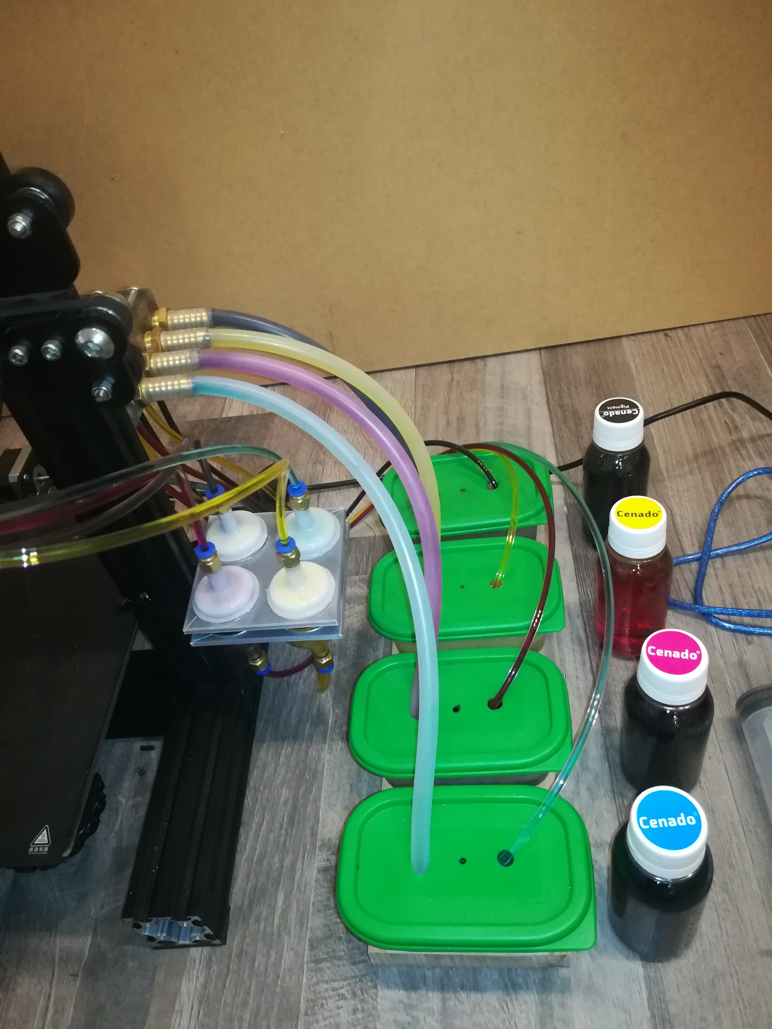
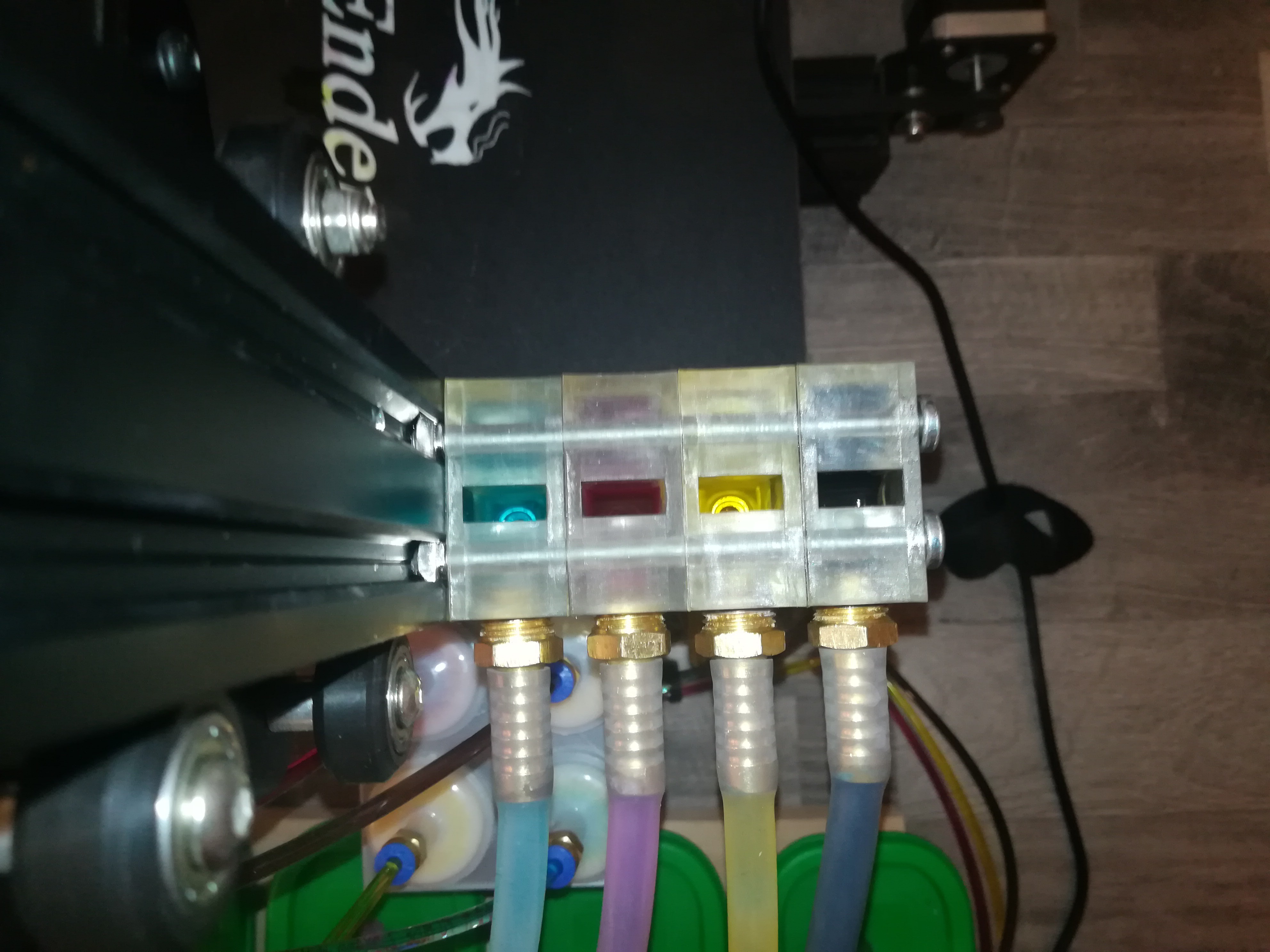
- CMYK Printing
- RGB Printing
- Part Labeling
- Binder Jetting
- Printing on Food*
- Bio Printing*
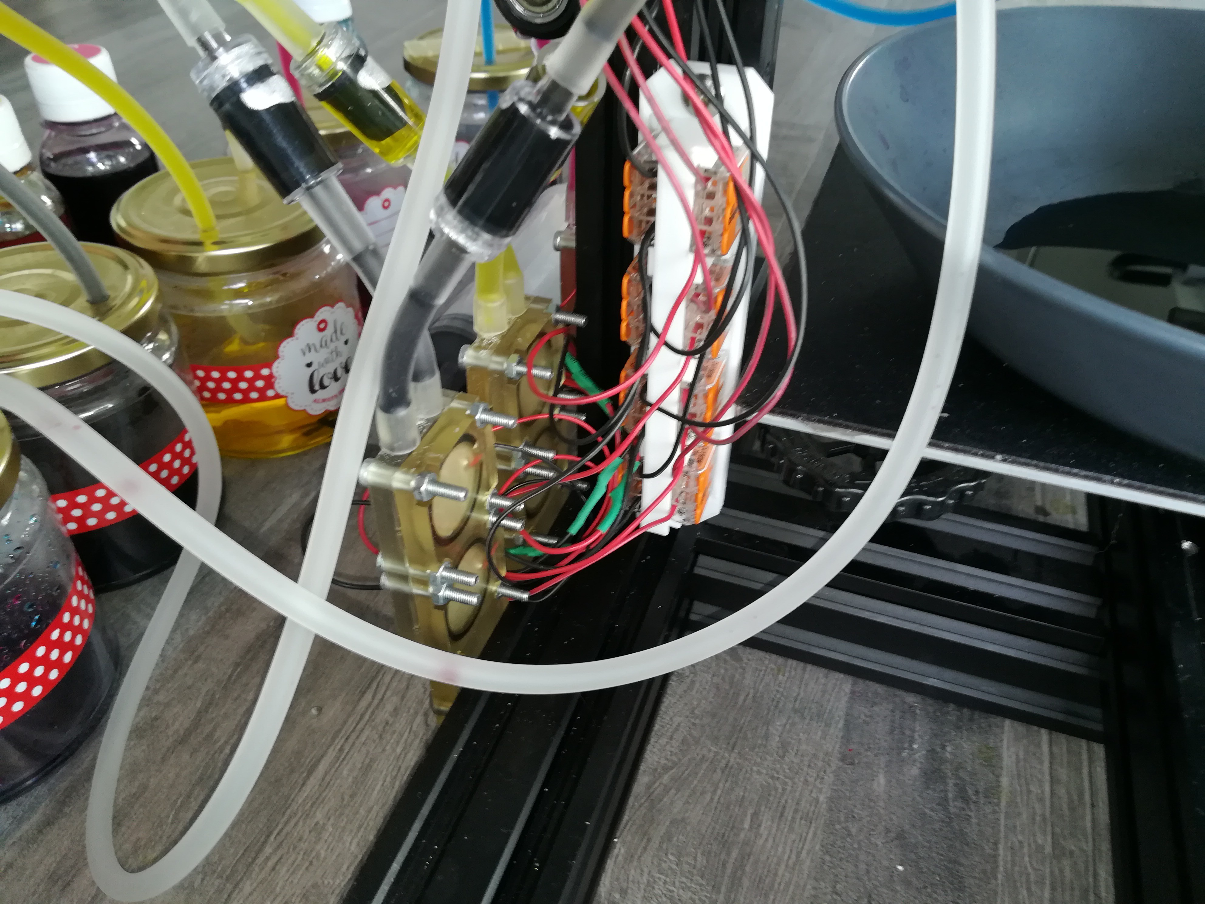
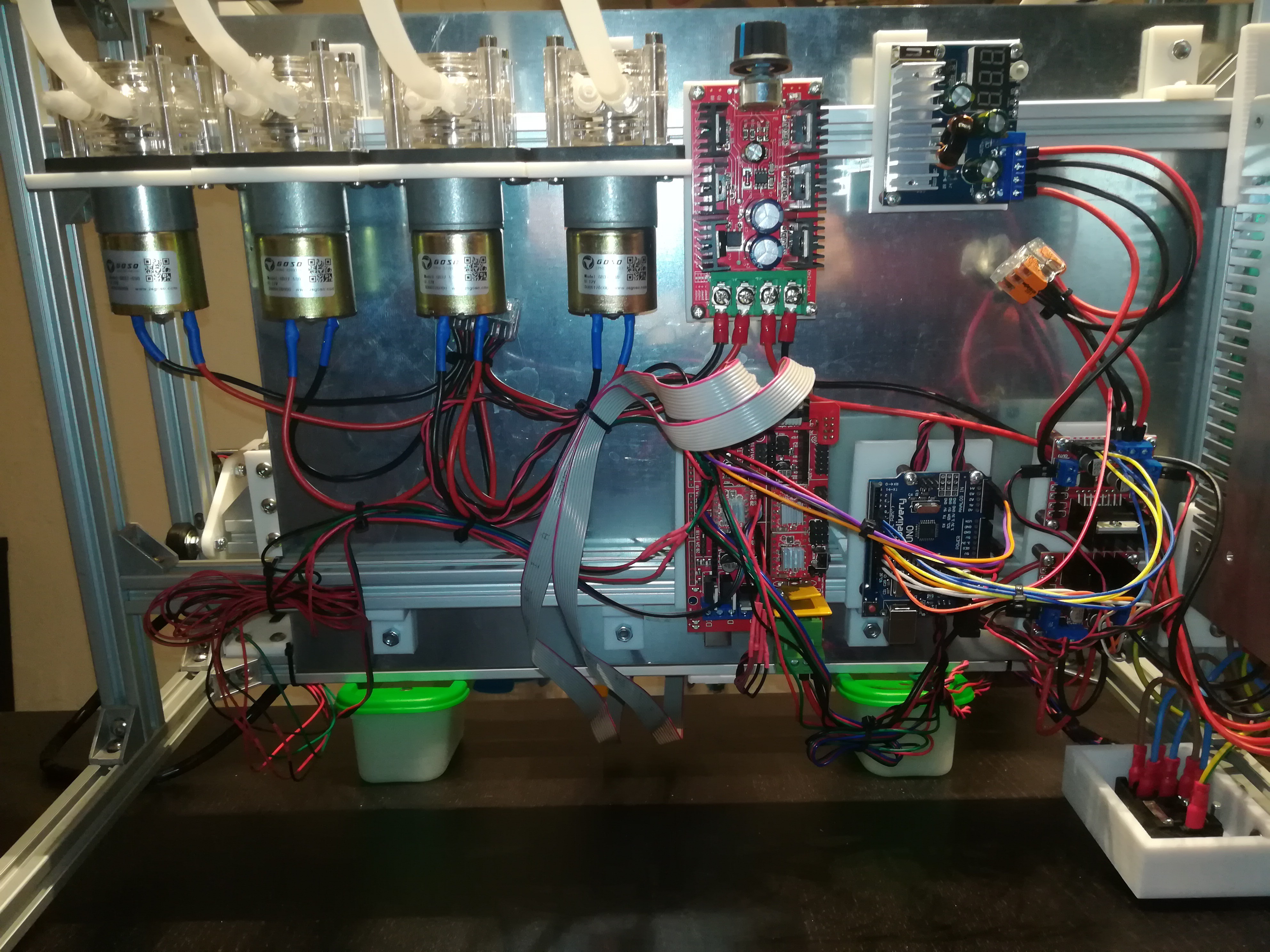
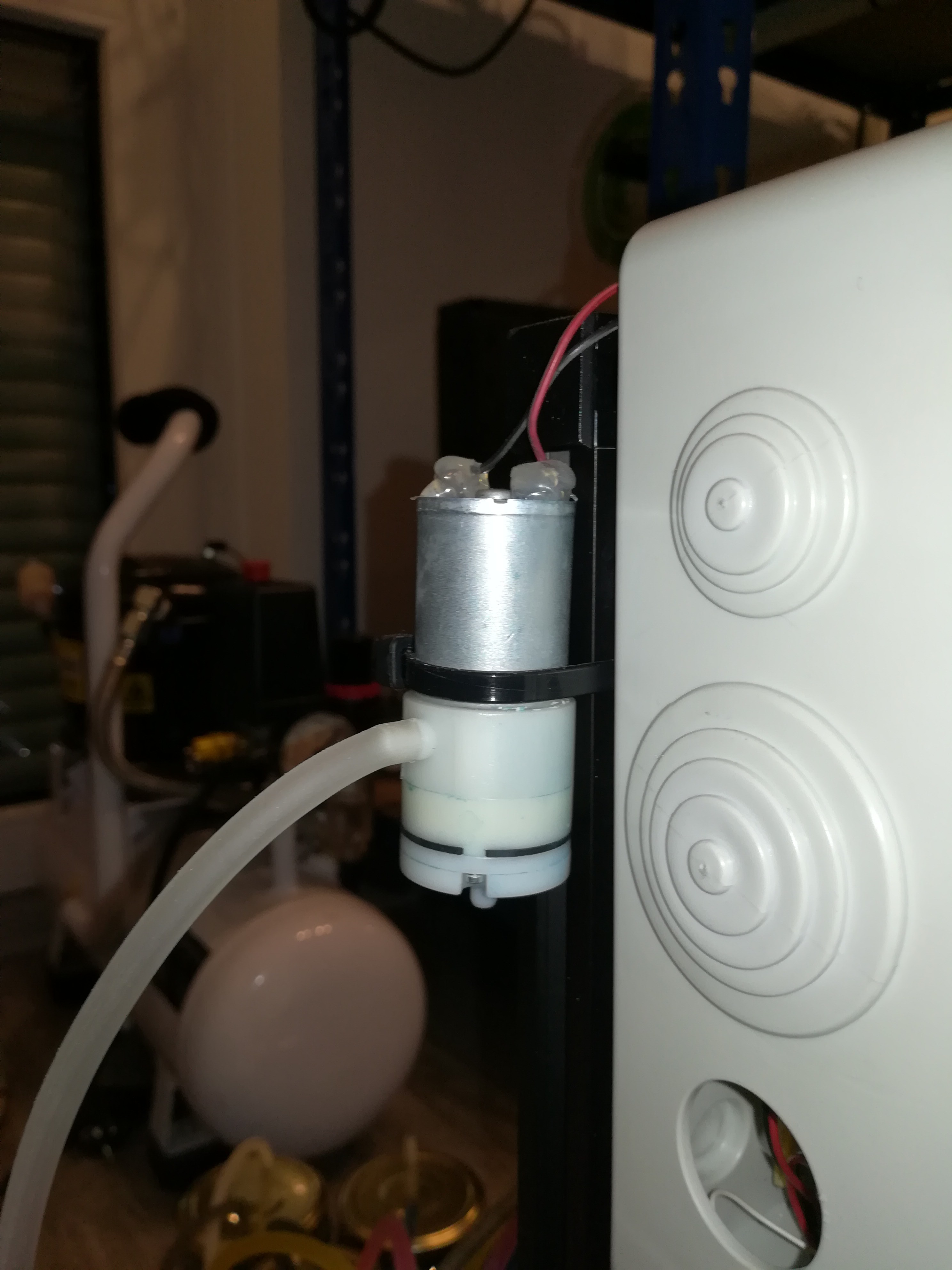
*The piezo pumps and printhead are currently made of SLA resin which is not food grade and must be replaced for these applications. The sealings and silicon tubes should be food grade and the piezo disc could possibly be cleaned up or sterilised to be food grade.


 Luke Brandon
 Starhawk
This printer looks amazing, and I'm considering it for tattoo printing. However, I've seen various machines on this page (https://tattoohutt.com/best-tattoo-stencil-printer/) Will they be suitable, or is it possible that they won't work? I am confused.