 Dominik Meffert
Because the current design with hydrostatic pressure fed prindhead has some reliability problems - sometimes one of the four heads starts dripping or sucking in air before or during printing - I'm working on a possible solution right now.
My plan is to build SLA 3D printed Piezo Micropumps to either feed ink to the printhead according to ejected drop count or integrate the pump directly into the printhead, so that the printhead can draw ink form the ink container.
I designed and assembled a pump and later today I want to test it.
I also bought flexible resin for printing the check valves in the pump which are currently printed from the transparent resin that I used for the printhead.
Update .... Success
After a week of failing on building all piezo micropump designs that I found on the internet I finally got something to work. I tried out pumps with 3D printed valves and valveless diffuser nozzle and channel design, but they did not work. The last thing I tried was using the latest inner channel pump design, connecting two duckbill valves to it, priming it and - because of the lack of a 100V+ piezo driver or parts to build one - connecting a 115V AC transformer to it.
And out of a sudden after days of failing - It worked!
I guess it's actually really simple you could for example if you stay with the 50Hz from mains use a small transformer and some SSRs to control the flow by the ON time to precisely dose the ink. It could work by counting the ejected drops, like after some amount of drops let the pump run for some amount of time or pump run time per drop in milliseconds.
Until now the printheads were fed by hydrostatic pressure and I have not tried out if they would also work when they are feed by pump, so I need to test it first.
The former ink cycle could likely be replaced by the pumps if you don't need mixing or want to use a big ink container.
If you would use the same driver setup it would likely replace the four pumps and step down converter with a small transformer, four SSRs and four piezo pumps.
I also tested out to run the pump with just one piezo instead of two. It did also work, but the flow rate was really low and so I think it would be better to use two piezos and limit their On time instead.
I tried out to switch the pump with a SSR because I had some concern that because of the piezos being a really small (as far as I know) capacitive load it would not work, but it seemed to work. Because of the SSRs leakage current they do not entirely turn off, but in the off state the pump has not enough power to lift the liquid so that it should not be a problem.
I also ordered an 8 channel SSR module to try the 115AC for the printheads, too.
New more compact pump design
I changed the pump design to be more compact and also replaced the 4mm PU tube + M6 fittings by 6mm silicone tube + tube connector integrated into the part.
I did not integrate the duckbill valves into the part, so that you don't have to find the right sized one and can instead buy check valves that fit the tube diameter if you want to build the pump.
I think for the connections it would be the best to secure them with a small zip tie or something similar to make them more seal and to prevent them from getting loose.
I tested the new pump and it worked very well. And I also ordered different filter which are placed at the end of the tube in the ink container - the ones for chainsaws and lawnmowers.
Update:
The pump in the picture had a height of 5mm and also a tube connector with 5mm diameter. Because of the printing process one side of the tube connector got a bit flat/not perfectly round and therefore the tube connector got a bit leaky.
So, I'm currently printing one with a height and tube connector diameter of 6mm to get a tighter fit and hopefully get a sealed connection.
I also thought about designing a pump which would have the in and outlet at the top to get it even more compact.
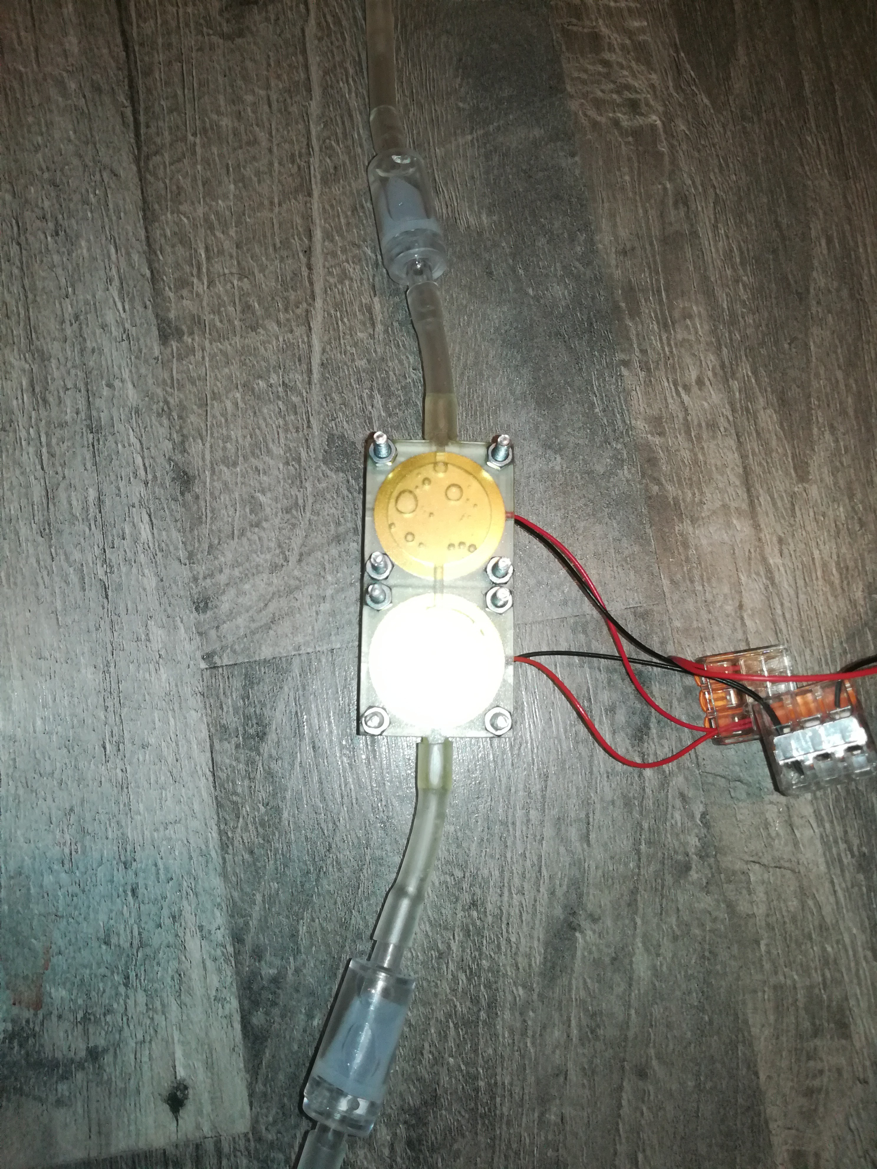
Two Chamber Piezo Pump:
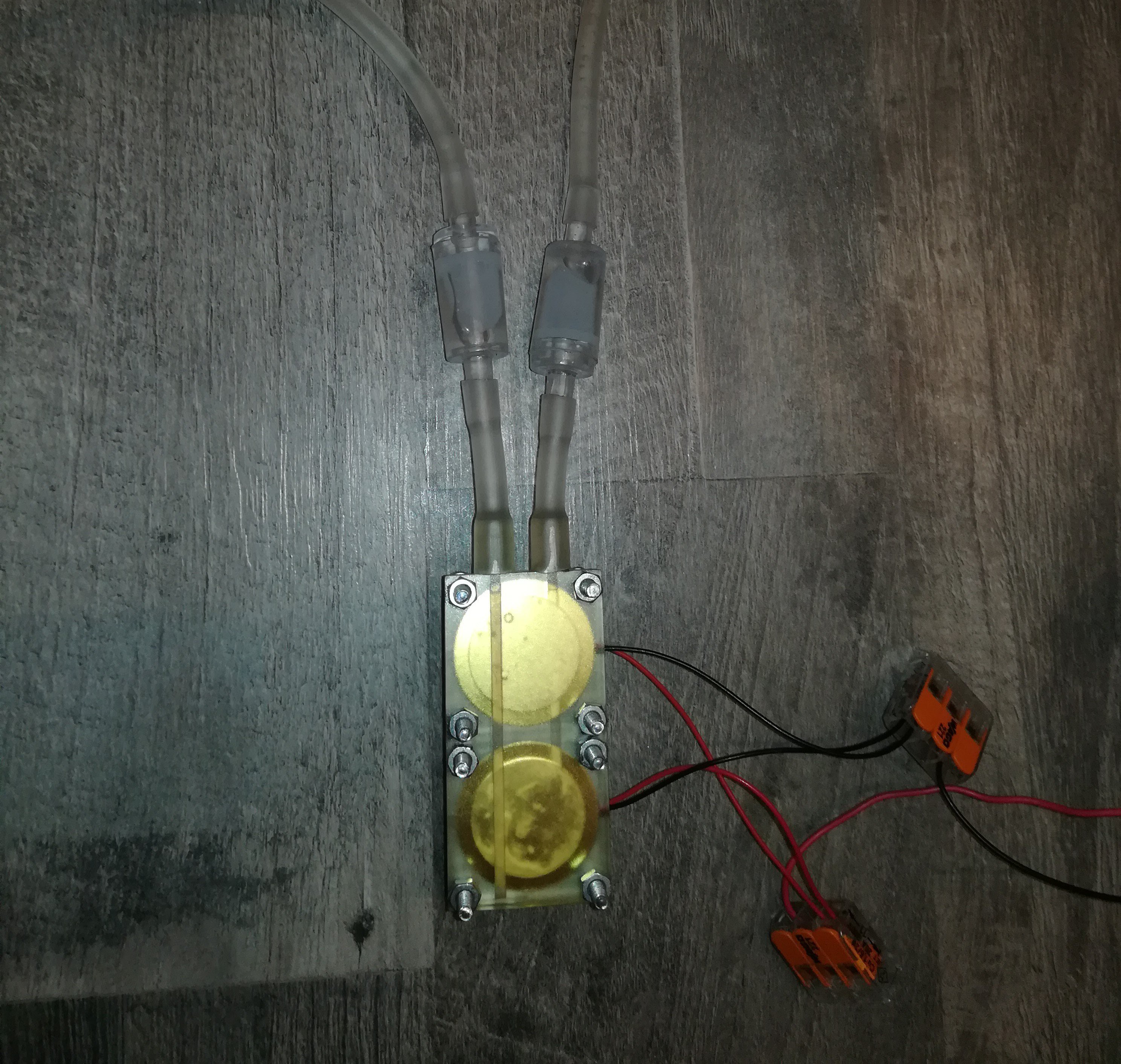
Here is another pump design with two chambers, the in and outlet at the top and 6mm height.
The 6mm tube connector diameter and some filing to remove the ridge from printing had lead to a sealed and solid connection.
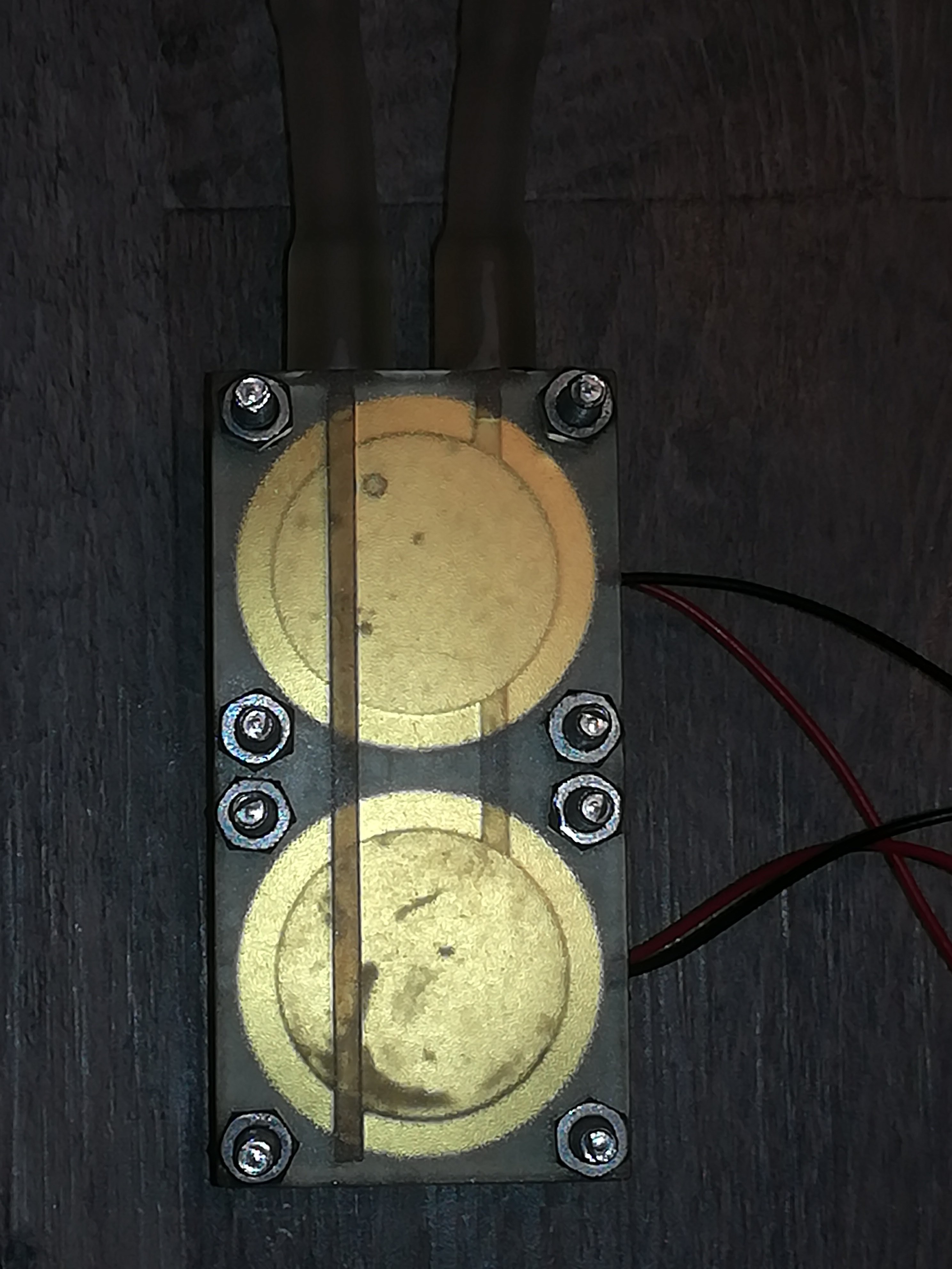
Inner channels to guide the fluid from the input to the bottem into the first and second piezo chamber and to the output.
I think this pump design should be good enough for using it on the project.
Short note: I had a small printing error in the printed part - a small hole on the back through which air could leak into the chamber. I think this was caused by an error with my printing setting or related to the resin and not an error in the design.
I fixed it by applying some resin on the part and curing it with an UV lamp to get it seal.
This pump design has two piezos but it can also be build with just one if the higher flow rate turns out to be not needed.
New Filter:
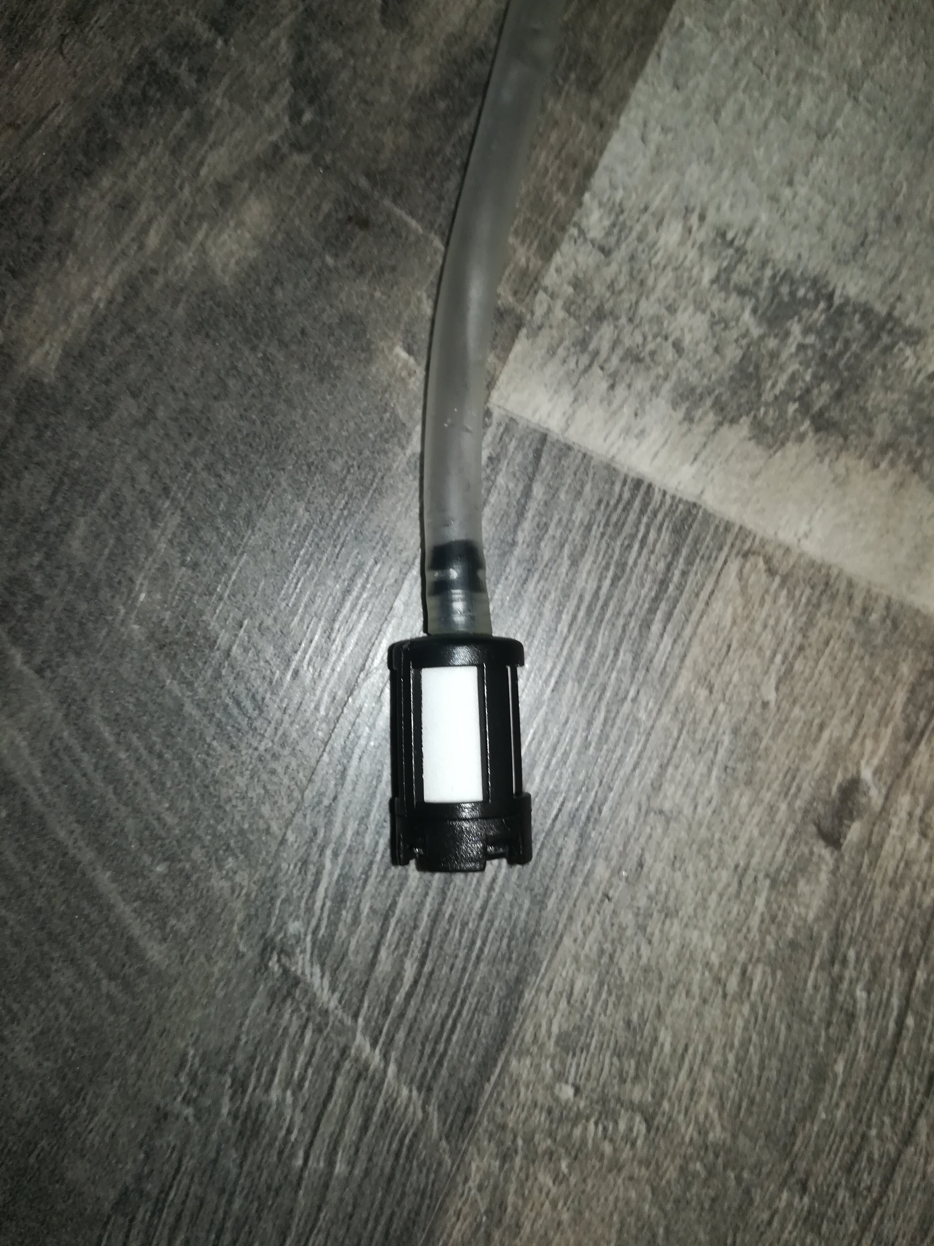
I got some chainsaw/lawnmower petrol filters to replace the larger gasoline filters.
Piezo Printhead no longer needed:
While testing out the piezo pump and piezo printhead I figured out that the pump on its own is able to eject dropplets from the printhead. That's a great thing, because with that the printhead can be designed a lot smaller because it only has to contain the nozzle and no longer the 27mm piezo disc.
Discussions
Become a Hackaday.io Member
Create an account to leave a comment. Already have an account? Log In.