The heart of this project was a NodeMCU (as I happen to have dozens of them lying around). Once I'm certain that I'm happy with the project, I may desolder the ESP8266 chip and rework my circuit to be smaller. Once the project was completed and ready to be installed I realized that I had made a horrible mistake. The original pump that came with the cat feeder was 12V AC not DC. This put a wrench in my plans. Instead of redesigning my circuit, I instead chose to purchase a generic 12V DC submersible pump. The reason for this, besides outright laziness, is that the original one would eventually fail, and I wanted to find a common replacement that would be easy to pick up in the future. Turns out there is a generic 12VDC pump that seemed like a good match and is sold all over Amazon and Aliexpress. Though a bit of a gamble, the replacement turned out to be a perfect fit with minimal required surgery.
There are no surprises as far as the circuit goes.The details of how to wire up the project can be derived from the schematic and the pictures. The DC-to-DC buck converter is used to drop the 12VDC that is provided from a typical wall-wart power adapter to 3.3V's for the NodeMCU. There are a couple gotchas with this step. First, the NodeMCU can be powered either by providing it exactly 3.3V on a 3V pin, or by providing it something more akin to 5V's on the Vin rail. Since power that goes through the Vin rail is subject to additional voltage regulation, more power is required. I recommend making sure your voltage is correct, and directly powering the NodeMCU via the 3V and G pins. Once you have the DC-to-DC buck converter properly adjusted (by tweaking the tiny potentiometer on board), I highly recommend place a drop of super glue on the pontentiometer to ensure it does not move. I've had a project get fried before when the potentiometer vibrated to a different position, resulting in a large voltage spike.
The new pump requires small alteration to fit into the cat fountain. This simply consists of cutting off the intake pipe to be flush with the pump body. A Dremel or hacksaw will work, though it is important to make sure to remove all lose plastic debris upon completion. See the associated picture. The new pump was slightly shorter than the old one, and the old one had suction cups on the base to keep it in place. I found that the new pumps outtake pipe was perfect to fit snugly in the base of the fountain top. This was sufficient to hold it in place. Unfortunately, this means the pump's low water point is higher than the old pump. In the associated pictures you'll see where my probes are currently. Though this works, the pump's pretty dry by the time the circuit detects low water. In the near future, I plan to move the one probe up about a quarter inch.
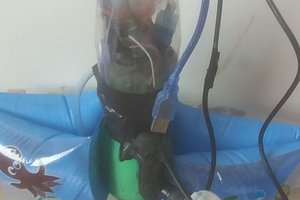
Lastly, we need to create the probes for detecting low water levels. For this, I took a couple zinc-plated finishing nails, soldiered wires around the tops, and added heat shrink to cover it. Then I hot-glued them along the inside of the fountain case. One nail should terminate at the "low water" mark you wish to detect. The other should be deeper. The zinc plating, along with only turning on power to the one probe while checking the water level is to reduce corrosion of the probes and extend their life. I found that the exit path for the pump wire was the perfect place to attach the probes (see associated picture for details).
From the pictures you might notice that I installed a barrel jack for power input. Unfortunately, I didn't have a matching power-supply adapter cord male-end, at the time. In my haste to get the project finished, I temporarily bypassed the jack. Eventually I'll have a proper jack and adapter, but I left that out of the BOM.
The code should be pretty self explanatory, but if it isn't, here's a high-level explanation:
Every CHECKDELAY (2000) milliseconds, the Arduino powers one of the probes...
 Shreyasvi Natraj
 Fabio
Fabio
 Bharbour
 jeffebin