 Owen
OwenConcept:
This is a low cost and lightweight temperature and status monitor for 3d Printers using Duet (or other repRap Firmware) controllers.
The Controller connects to the PanelDue serial port on the Duet card, and periodically queries the Duet Firmware for It's status and temperatures, then updates it's display as appropriate.
- Atmega328P based (as per the Arduino Uno)
- 2 x 0.96' OLED displays on individual I2C busses
- Level Shifter for Serial connections (duet is 3.3v, 328p is 5v)
- A button for pausing, a LED to show we are alive and a case to show off
- All the software is complete and tested, this was more than half the work..
- I include the full KiCad project, exported Gerber Files and more.
- The compact single-sided PCB is optimised for home production with a CNC or chemicals. It has generous pads, tracks and clearance widths.
- I do not provide detailed build instructions; You need to be confident you can do things like 3d print cases and make PCB's if you wish to follow this project. All the sources are provided but none of the technique ;-)
The two OLED display panels have fixed I2C addresses which conflict; so I create two separate I2C busses on the controller in software to drive them independently.
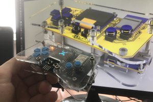
The completed project:
- Only displays very basic info: Status, tool and bed status + temperatures, percentage printed.
- Periodically sends
M408 S0status requests to the controller and processes the Json reply to obtain values. - Responds to some 'config' Json for update speed, brightness, timeouts and more
- Sleep mode when controller reports PSU off, (configurable).
- Activity LED and Pause button are fully configurable.
- Clearly shows when heaters are in a fault state.
- Plug-n-play with panelDue UART port, powered by the port itself.
Software
https://github.com/easytarget/PrintEye
Project time was spent mostly in developing the Software; this was the most challenging part of the equation for me; I learned a lot doing this, which was the whole point of the exercise.
Please read the README file in the software repo for a proper description, requirements and documentation
I developed using the Arduino IDE and programmed the prototype via a FTDI adapter while testing using the serial terminal. The project was nearly complete before it was ever connected to my Duet controller. And when I did that, it worked first time :-)
Hardware
https://github.com/easytarget/PrintEyeHardware
In the release packages and Github repo I have provided the Full KICad project I created; including custom component and footprint definitions for the OLED displays.
The ATMega sits on a standalone PCB; it has a very 'vanilla' crystal and reset circuit; the OLED displays are driven directly, they already have appropriate pullup resistors onboard. The RX/TX serial lines go through a very basic bidirectional 3.3v level converter for compatibility with the Duet controller.
The UART port on the Duet controller provides a 5v power supply; and I designed the PCB with a FTDI connector facilitating in-place reprogramming with any suitable programmer. The Duet is connected via the same connector using an appropriate cable to bring power and serial comms.
PCB
Gerber files for the single-sided PCB are included in the Hardware Repo
- There are three bridges that need to be placed on the top side.
- The FTDI connector needs to be placed on the reverse (copper) side of the PCB.
- The PCB is optimised for Home CNC fabrication, using a vcutter for isolation and a mill bit or drills for the holes. All pads, track widths and clearances are generous.
Case
The included case is designed to have the OLED panels glued in place. The PCB then mounts onto their connectors.
- Glue it lightly! I used generic contact...


 Jeremias
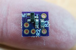
 Bud Bennett
 Phil Malone
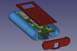
 Michael O'Toole
Hello, creator! When I finished the project, I encountered a problem and displayed the interface, but unfortunately it always showed 0. I don’t know if I didn’t do something right!