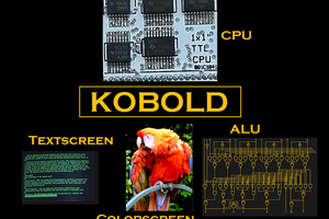
MOTIVATION
After having worked several months on the first Kobold CPU , I got the feeling that it was going in the wrong direction. I was working on a Javascript assembler, and got tangled up in the microcode complexity. I also didn't like that so many parts were needed to decode the microcode. So I decided to make a huge change in the design. Here is Kobold K2 !
So what will change ?
- Microcode is not used any more, instructions will be RISC
- Four new 16-bit data registers in hardware (now total 8 registers)
- The 8-bit ALU will change to 16-bit ALU
- All instructions need two cycles (fetch, execute)
The Kobold K2 will be faster, and its operation will be easier to explain.
The video system will stay mostly the same.
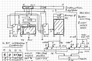
STRATEGY
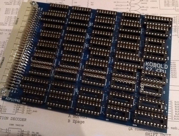
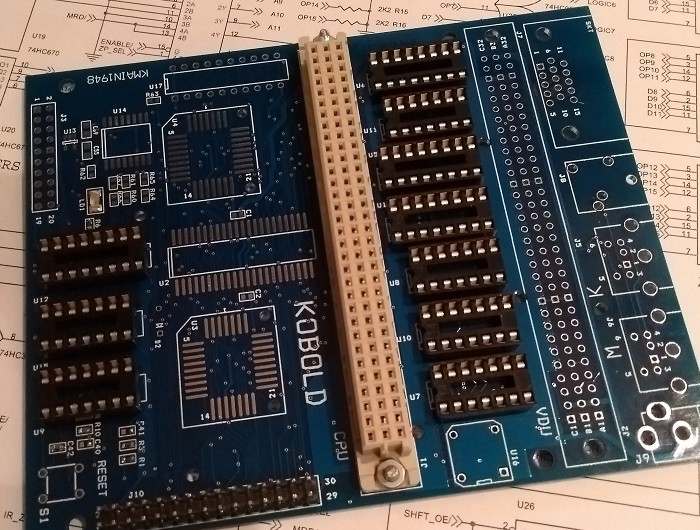
Finding the balance between low number of parts and high functionality is one of the key aspects of TTL CPU design (at least, for me it is). I want to keep the part count low, but not to the extreme as in #1 Square Inch TTL CPU. The CPU part of the computer should fit on a single PCB.
To keep the control system simple, every instruction should execute in a single cycle. If the ALU was kept 8 bits wide, that would mean 2 instructions for many 16-bit actions (as in the Z80 or 6502), and that would slow down 16-bit operations. Therefore, the ALU is now 16 bit wide. I don't want to use the 74181 ALU, so to keep part count reasonable, the ALU has only a few functions. The small number of functions also simplifies control.
The average performance per clockcycle is expected to be higher than that of a 6502 or Z80 and might come close to the performance of a 68000 in several situations. The performance is mainly due to the RISC strategy, fast access to 4 data registers and 4 address registers, and to having everything 16 bit wide.
VGA VIDEO INTERFACE
The VGA card provides 640x480, 32K colors, full color sprites, and sound !
SPEED
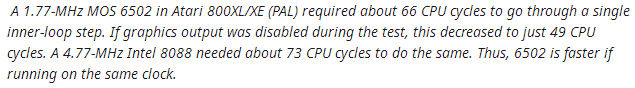
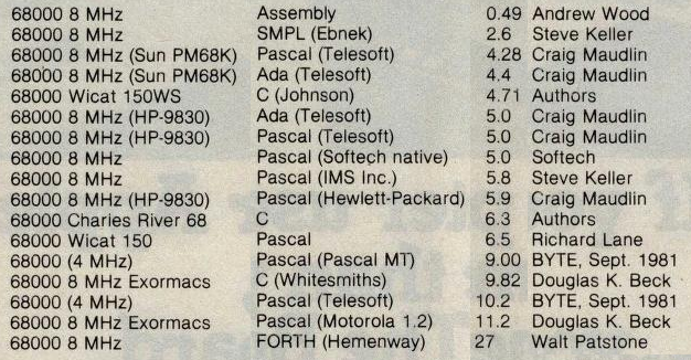
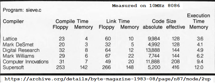
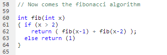
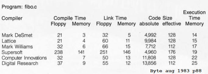
The speed of the Kobold K2 was compared to other processors, as described in How fast is this thing, anyway ? The Kobold K2 (at 6.25 MHz), running code compiled by its C compiler, is faster in all five following situations:

The 68000 did run a program that was compiled by a C compiler of 1983. Hand-optimized assembler code for the 68000 did run a lot faster than the Kobold. Comparison against the 8086 was also with C code on the 8086.
PROGRAMMING ENVIRONMENT
To make programming easy, an Online Javascript Compiler/Assembler/Simulator was made. The C code or assembly code for the K2 processor can be made and assembled in your browser. The C code can be written in the included online editor that has syntax highlighting, matching parenthesis indication and several other features. The C compiler is not yet full-featured, that's a project all on its own.
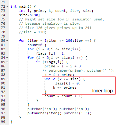
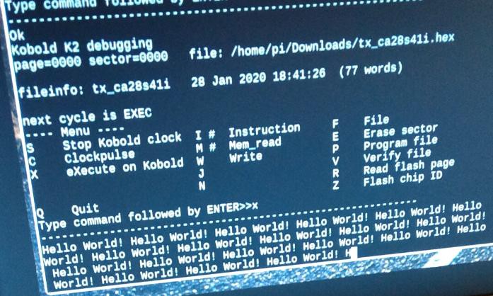
It can also simulate the cpu. If you open the simulator, just press Run to start the prime-number-generation demo ! In this window, you can also open the Manual to see which instructions and addressing modes are available. And of course, you can try to program yourself....
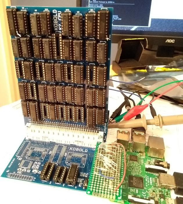
A Raspberry Pi can connect to the Kobold computer. On the Pi, you can make the application for the Kobold with the online compiler, then download the result to the Pi and put it in the Flash program memory of the Kobold (with a Python script).
LOGS
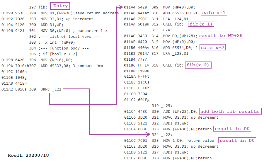
5. Subroutines
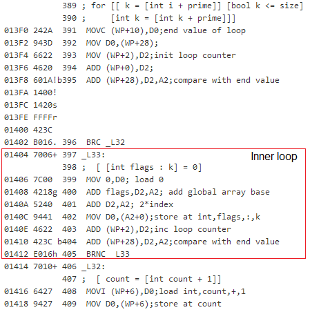
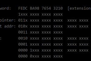
6. Instruction encoding and conditional branching
10. Changing the memory access model
11. More conventional instruction sequencing
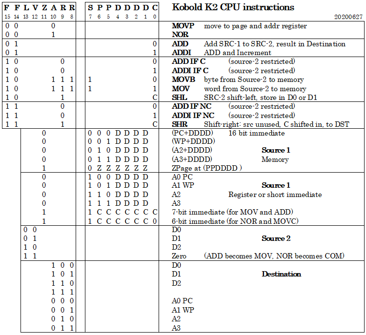
14. Instruction Map
15. PCB's ordered
16. Online Javascript Assembler/Simulator
Read more »


 zpekic
 Pavel
Pavel
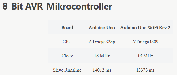
Comparing it to an NMOS 6502 (2MHz) seems really unfair especially when put next to modern AVR (20-24MHz) since the modern 65C02 (14-16MHz) exists. anyways i love TTL Projects like these, good work man! i would love to make a TLL CPU myself but just the amount of logic needed for a somewhat versatile ALU is pretty insane... maybe one day i'll get around to it. or i'll just "cheat" by replacing the ALU with a single CPLD.