 Jason
JasonSince I was now going to re-build my LED controller’s power supply for the 3rd time as I was getting ready to add another project to the central PDU; I decided to go big. Include everything I needed with room to grow. Add power monitoring so I know what was being used and whether I was close to overloading the power supply.
Since DIN rail terminal blocks and breakers are easy to sources, standard size and easy to move; I decided to go with a din rail setup. Cable management will be an requirement to keep everything looking good. The management outside will be cut at 45deg angles to keep the faces looking clean. The unit will be mounted to some shelving I have in my basement using some u bolts.
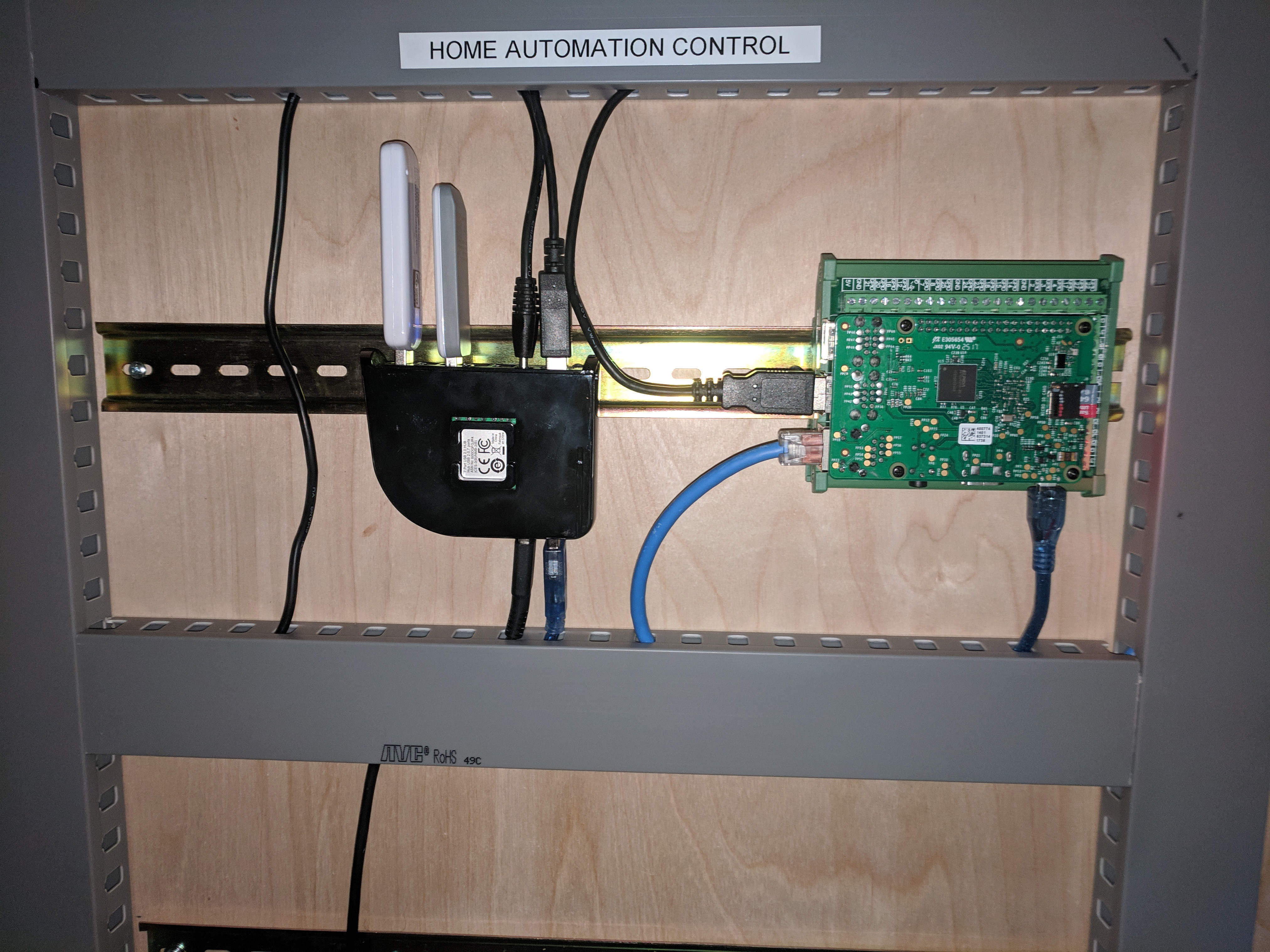
Since my RPI3 that controlled my home automation was just sitting on a shelf, I decided to also include it in this project. I got a DIN rail module that included a terminal block for the GPIO header so I can use them at a future time to provide LED status lights for the home automation or provide future relay control for the LED PSU. The USB hub powers the PI and interconnects the Z-Way and Zigbee USB hubs.
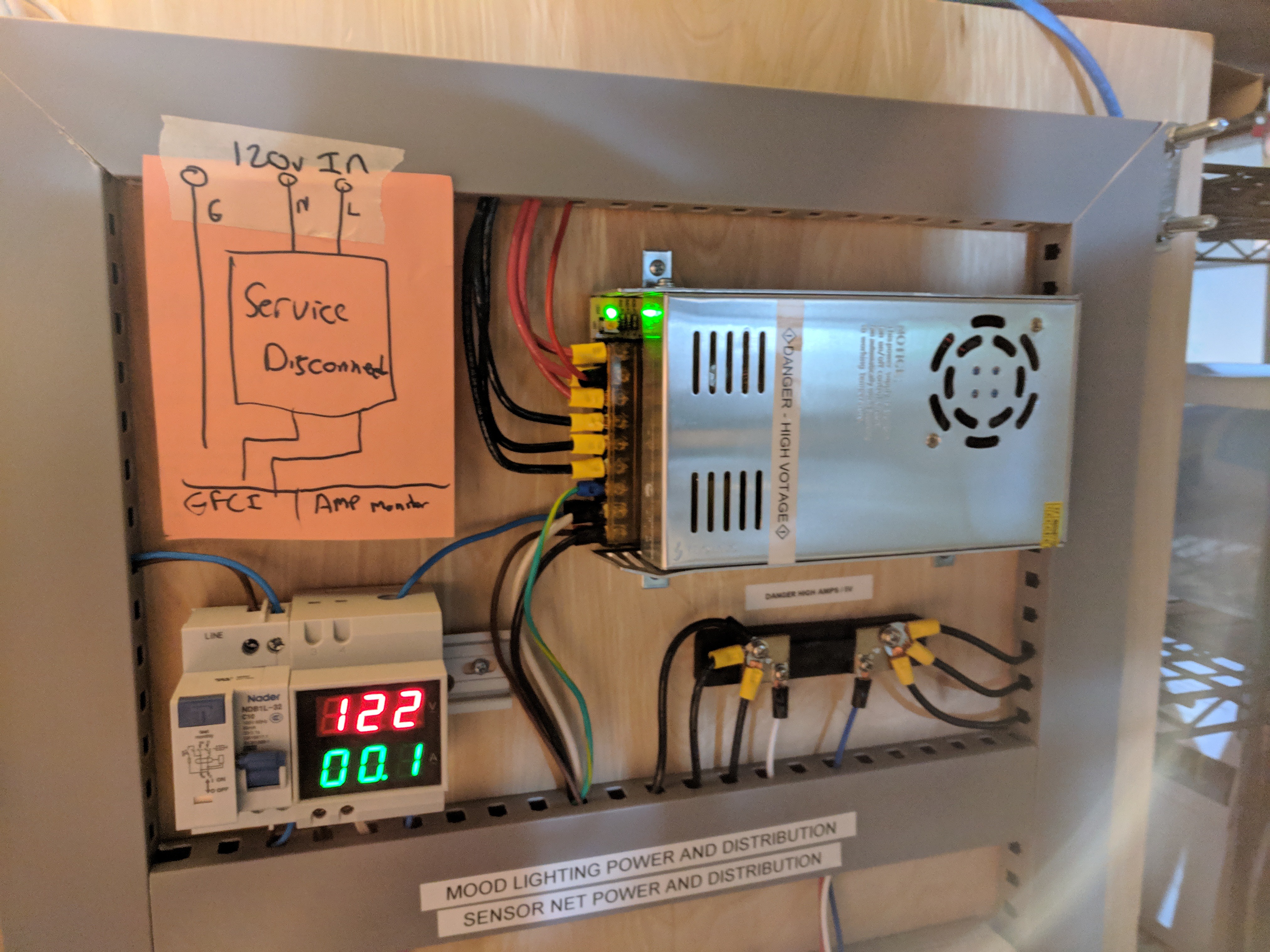
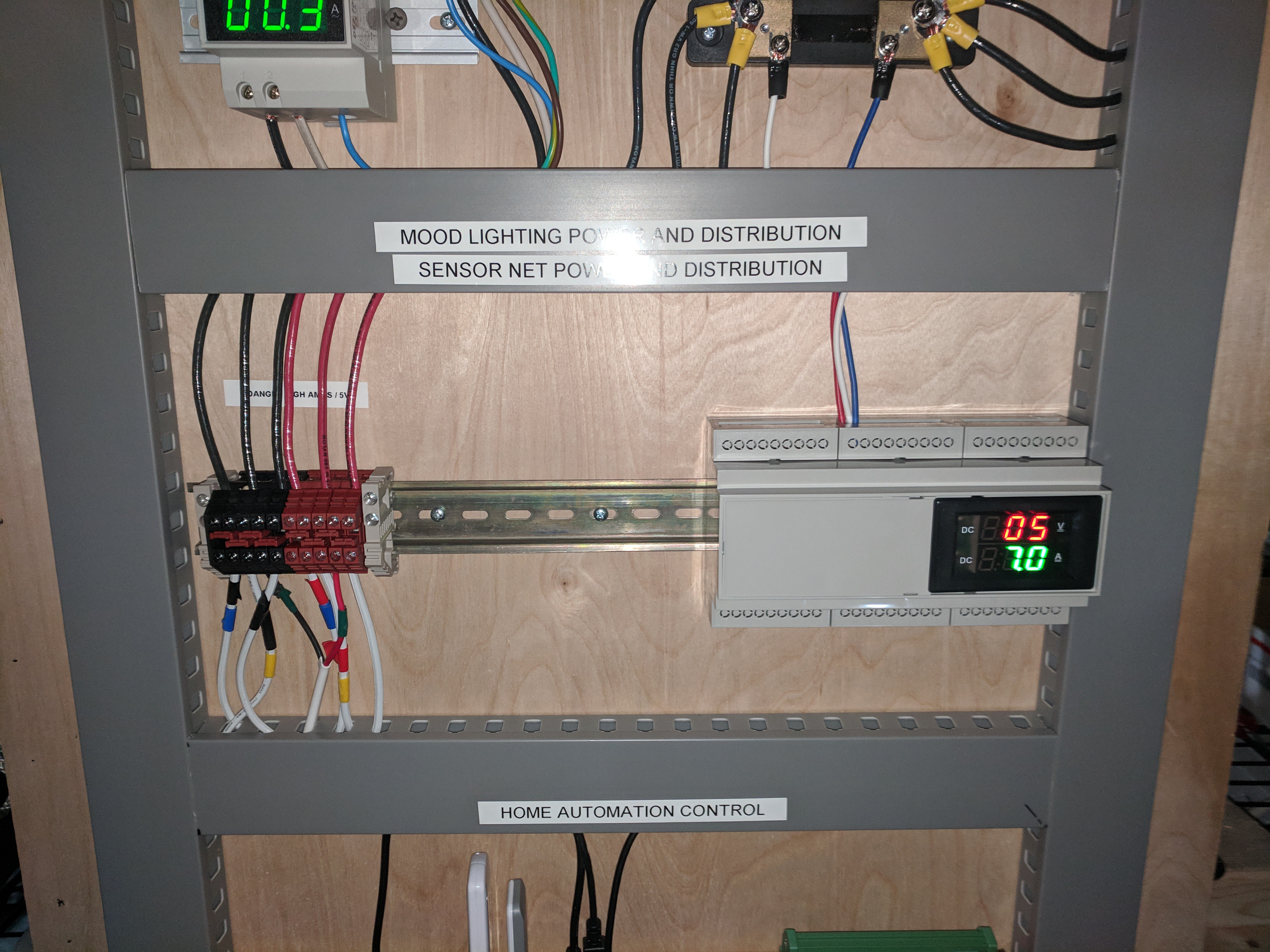
Both the high and low voltage systems have volt and amperage meters so I can monitor the load on the system and make sure everything is operating normally.
Safety add-ons:
Since taking these photos; I have added a ground loop on each DIN rail to prevent a nasty surprise if a hot wire hits a din rail while I am working. On the low voltage system, the power supply has builtin short detection and will kill power to the low voltage side of the system. On top of that I added a GFCI break to the high voltage supply to kill power to the system if something or someone hits a high voltage wire.
Plans are in the works to add 5Amps and 10Amp breakers for each LED strip so that an issue in one part of the house won't cause a major issue. Additionally a service disconnect will be installed to isolate the power for the PSU. Currently I have to unplug it from the wall.
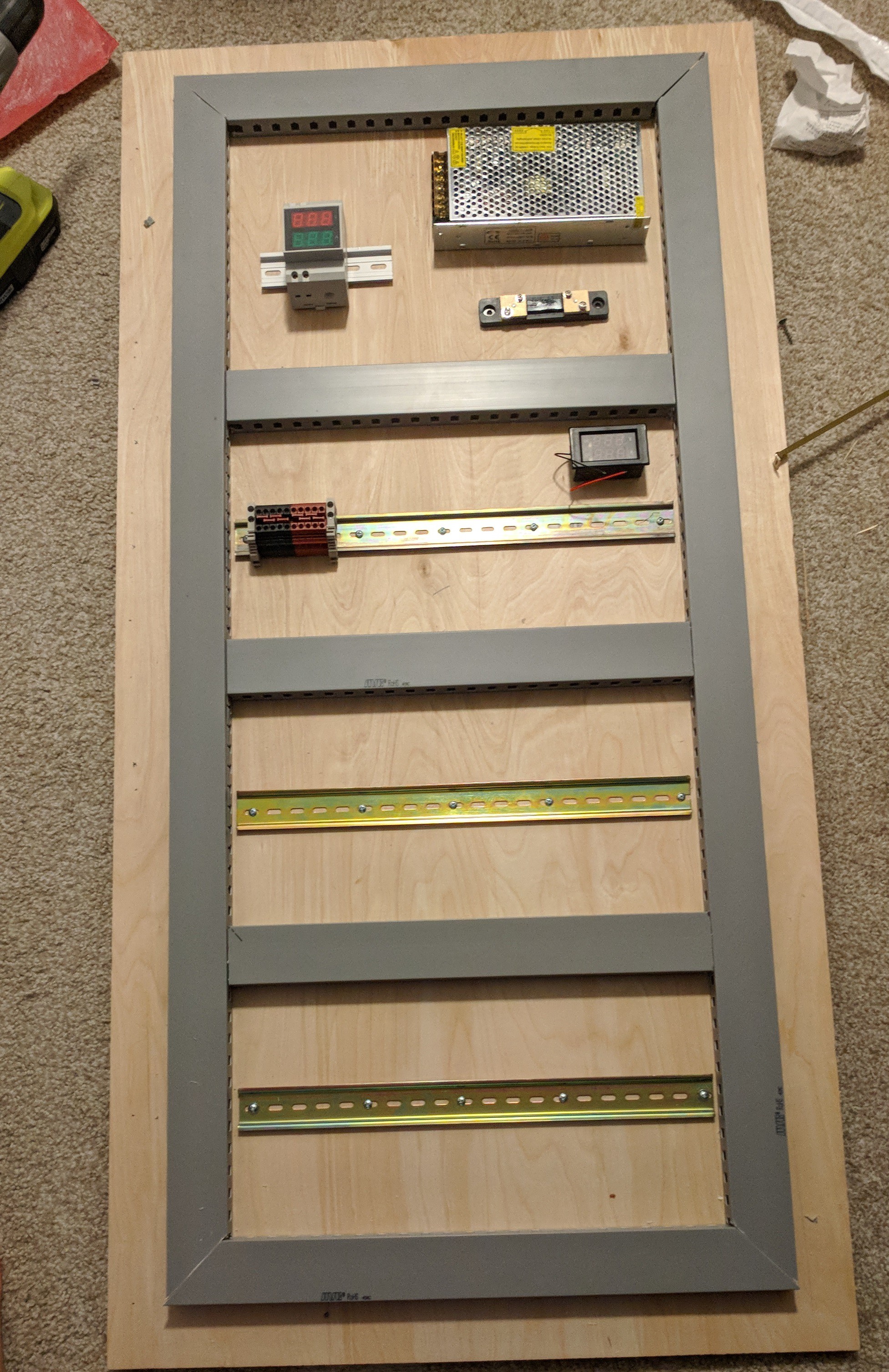
Testing Layouts:
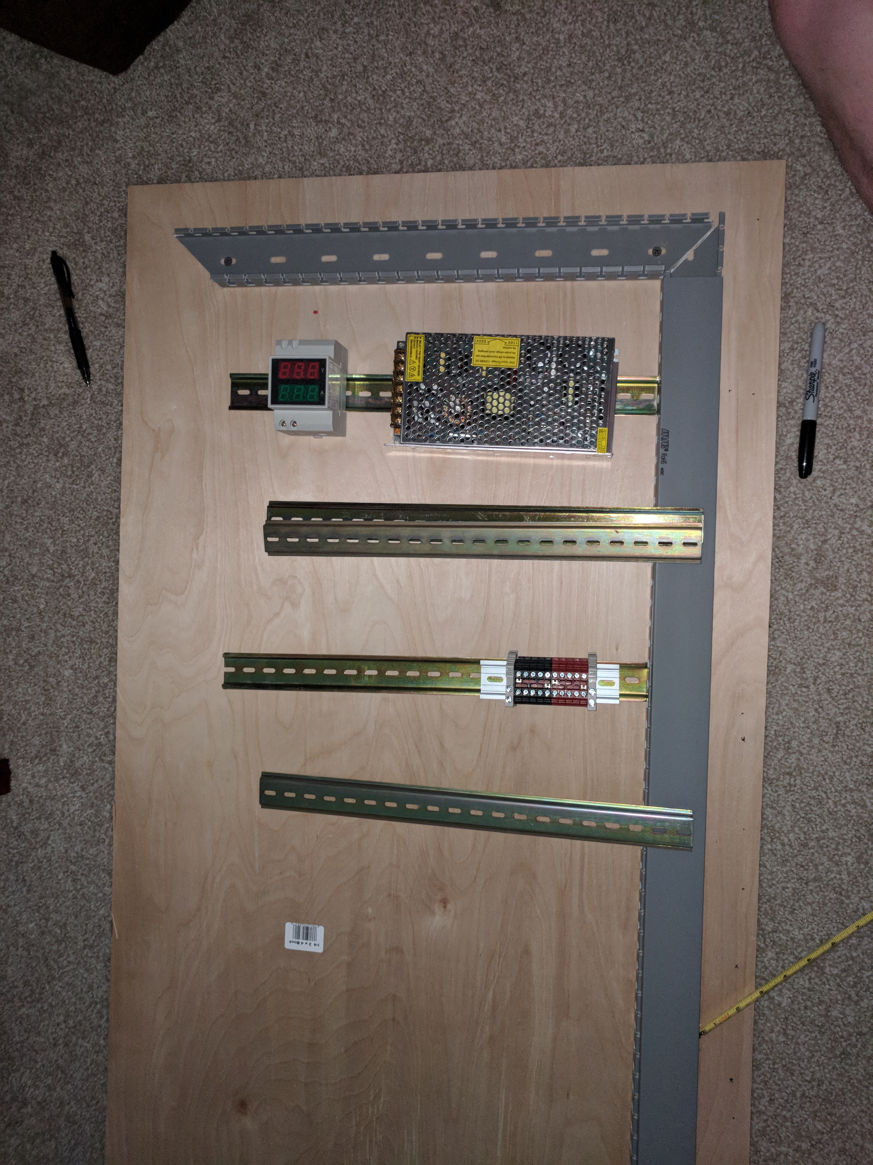
Final Layout. One(ish) section for high voltage, once section for low voltage, 1 section for the PI and 1 spare section:
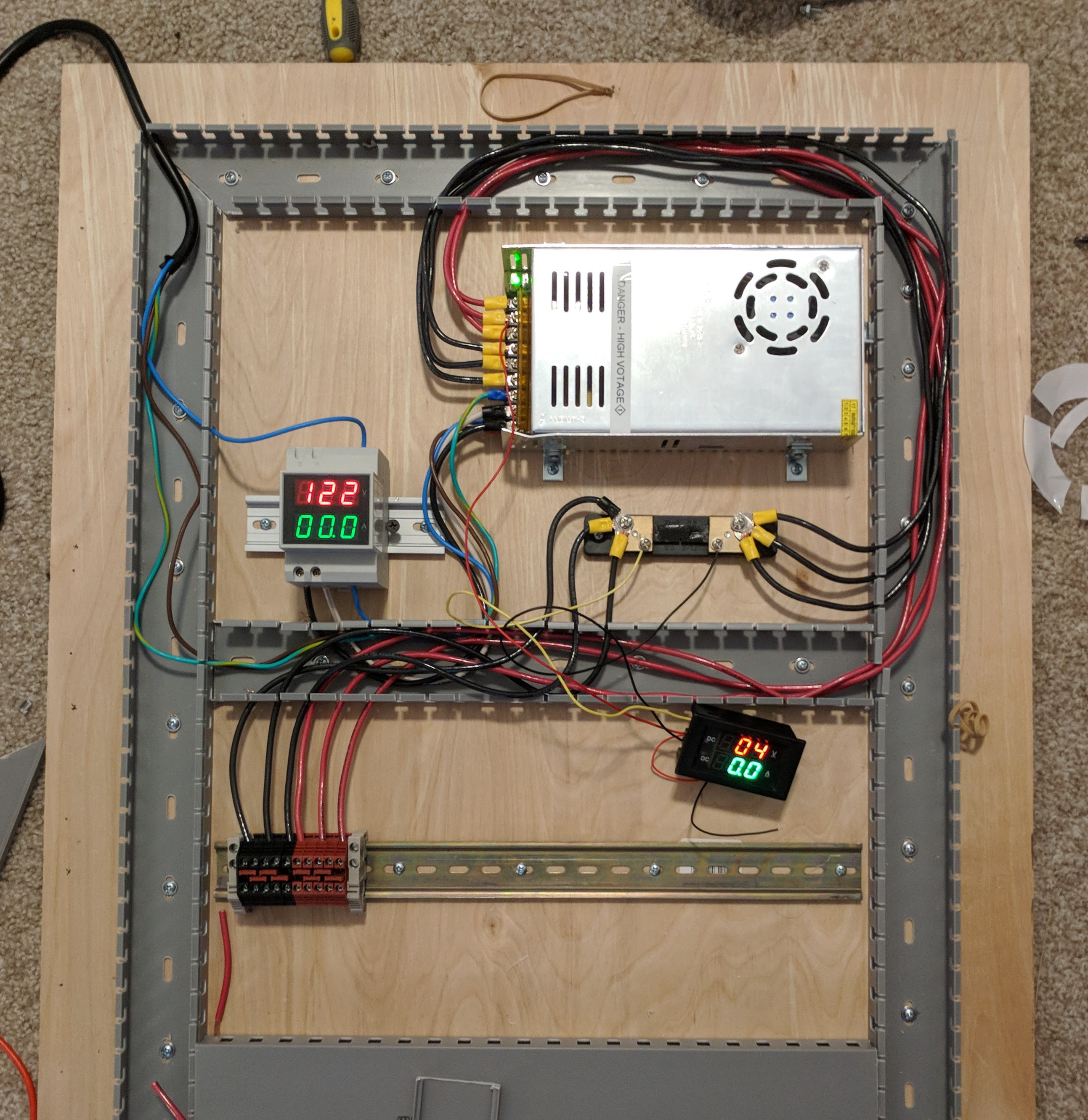
Cables ran and first power up:
PI mounted the the module. Mounted to the shelving:
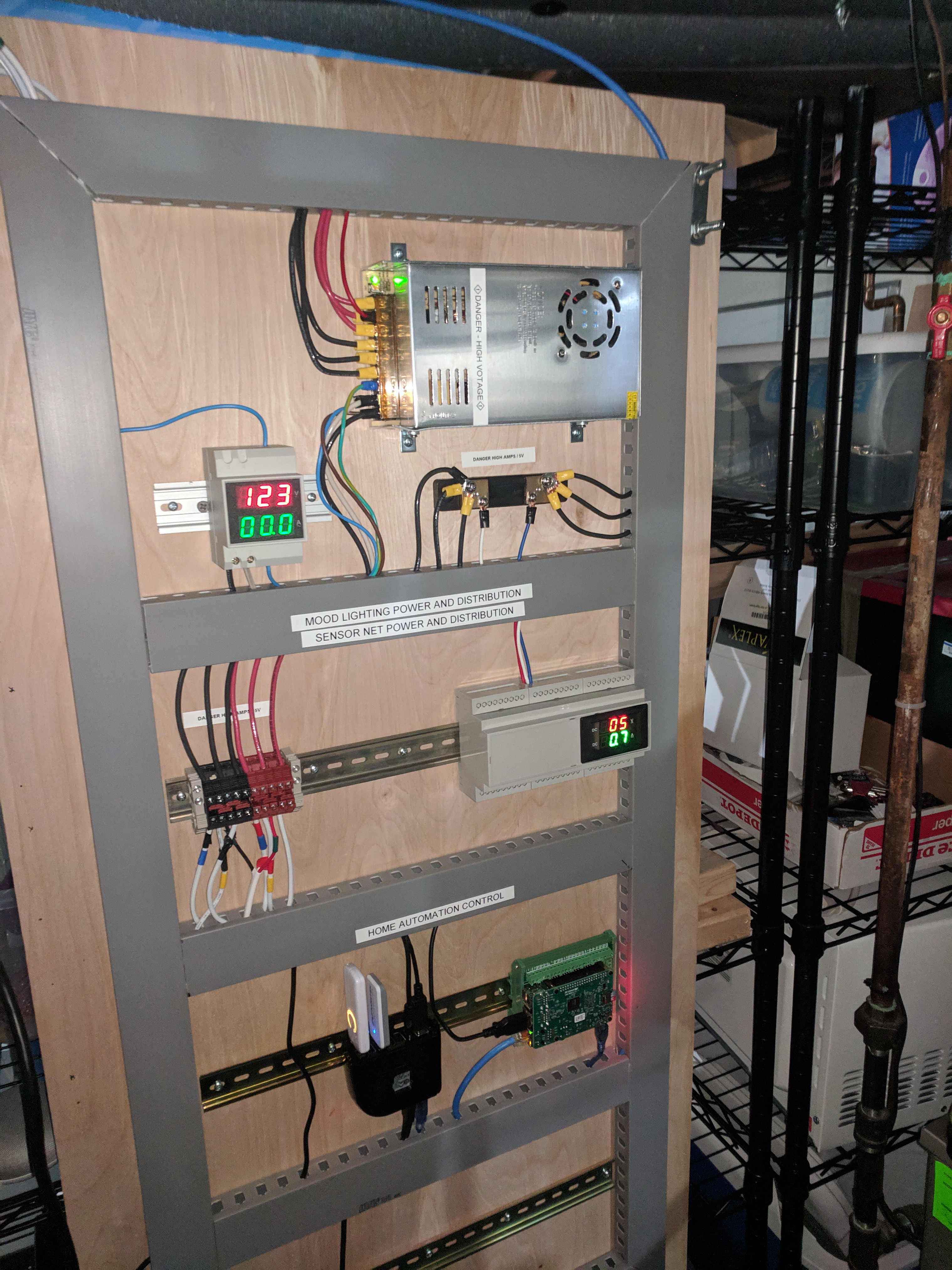
High voltage section and future home of the service disconnect:
Low voltage section:
Home automation section:
Discussions
Become a Hackaday.io Member
Create an account to leave a comment. Already have an account? Log In.