Close
0%
0%

Internal USB 2 hub with header pins

Internal USB 2 hub

Public Chat
Similar projects worth following
155 views
0 followers
Many USB accessories only use one of the 2 ports on a motherboard connector so I designed a hub to fix the issue.

Looking around online I found several schematics that were close to what I wanted but no cigar. The hub needed to plug onto an internal USB header with optional power to it, with a pass through of the unused port of the header. The hub needed to have pins rather than sockets to suit accessories intended for internal connection.
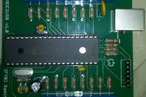
I messed up the mk1 pcb by missing 3 components, these were bodge wired on to get it working, the other issue was that it obstructed the 2nd motherboard USB header requiring a move.
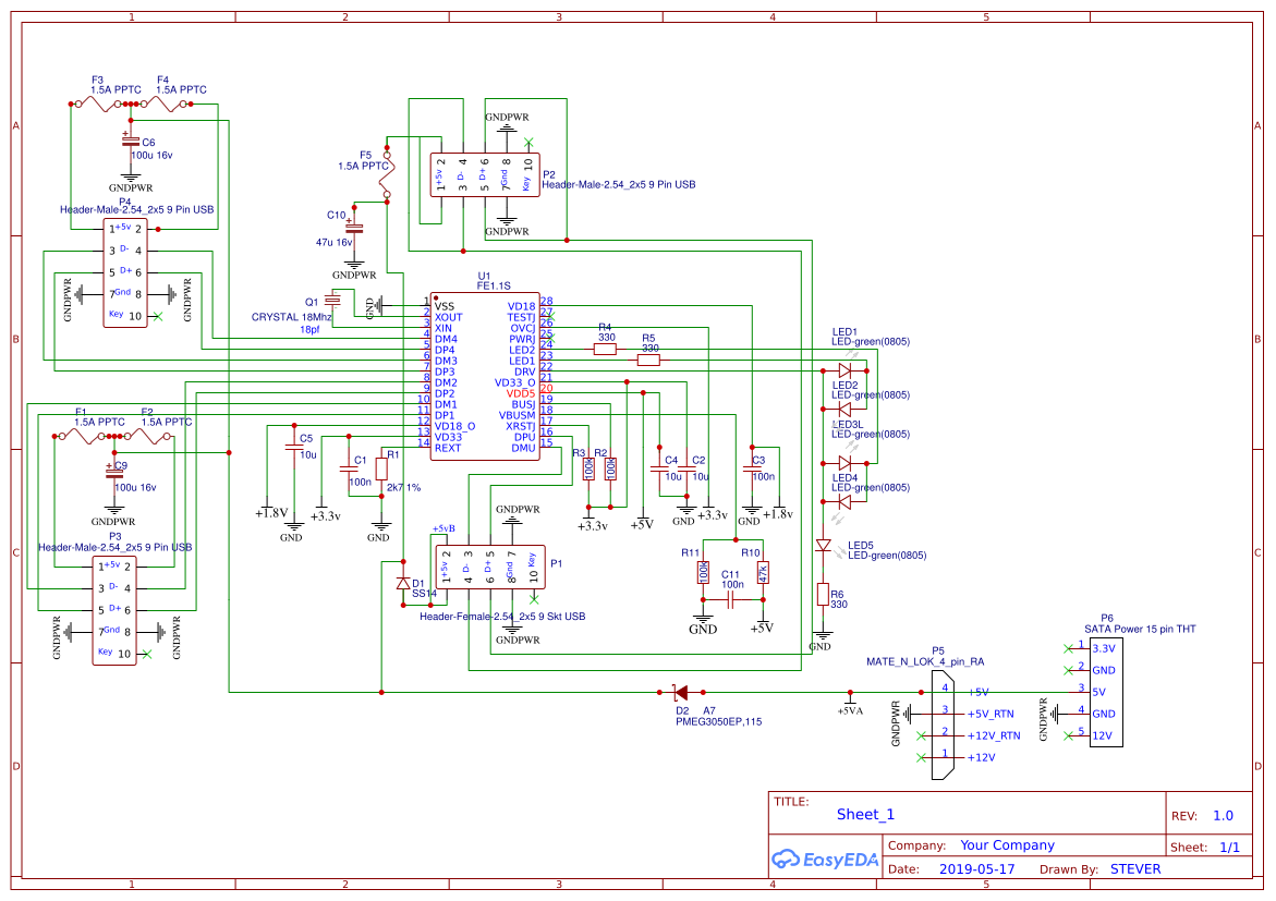
The hub chips do not monitor the actual current as when powered it is external to them so I included PPTC fuses on the power outputs, equally when unpowered 100uf caps are there just in case. Due to headers not having the same spacing as sockets it is only necessary to have one cap per header :)
I am uploading just the schematic as that is working, ( the MK umpteen pcb's are in the post  ), actually 2 versions, one with the motherboard connection central and the other offset.

The PWR suffix on the schematic is used in the design rules for auto routing with a track width of 1 or 2mm, non PWR tracks are .3mm wide, the latest pcb is manually routed and far more tidy than the early auto routed version.
Track impedance of the differential pairs (90 ohms for usb2) was done using  https://www.eeweb.com/tools/edge-coupled-stripline-impedance

  • Flaky on the pass through

    steverddrf11/02/2019 at 19:58 0 comments

    The latest boards work but the pass through port is flaky probably due to the length of the tracks from top to bottom of the board, 50% of completed boards work with an active device but not with a simple flash drive. The other 50% cause windows to give the same error even with an active device :(
    PCB's being redesigned to move the pass through port closer to the connector to the motherboard which should resolve the issue :)

    Another issue was too much solder paste bridging the SSOP28 chip requiring mopping up with de soldering braid, the next stencil will have the paste mask reduced from the default, the stencil is that recommended for SSOP28 at 12 mil thick.

  • I messed up :(

    steverddrf10/14/2019 at 23:59 0 comments

    The mk2 pcb's work ok but they have issues such as that they will not fit most motherboards due to there being no standard for where the motherboard ports are placed, the external power was fed through a 1 amp diode, and I forgot to do the Impedance of the differential tracks :(

    Back to the drawing board for the mk3 pcb and higher power diodes are on order, watch this space :)

View all 2 project logs

Enjoy this project?

Share

Discussions

Similar Projects

Does this project spark your interest?

Become a member to follow this project and never miss any updates