0%
0%
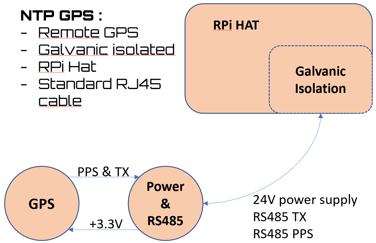
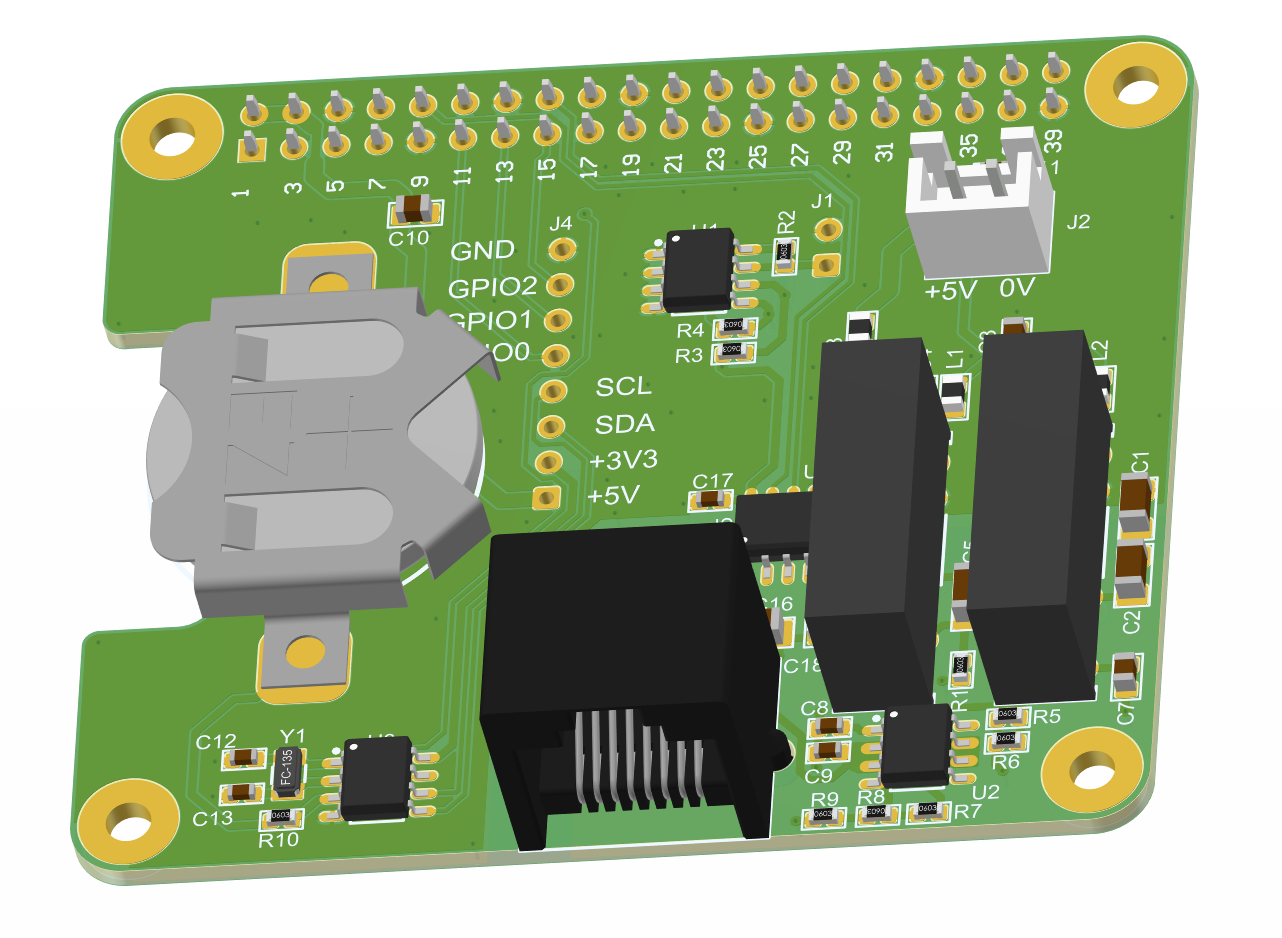
NTP GPS
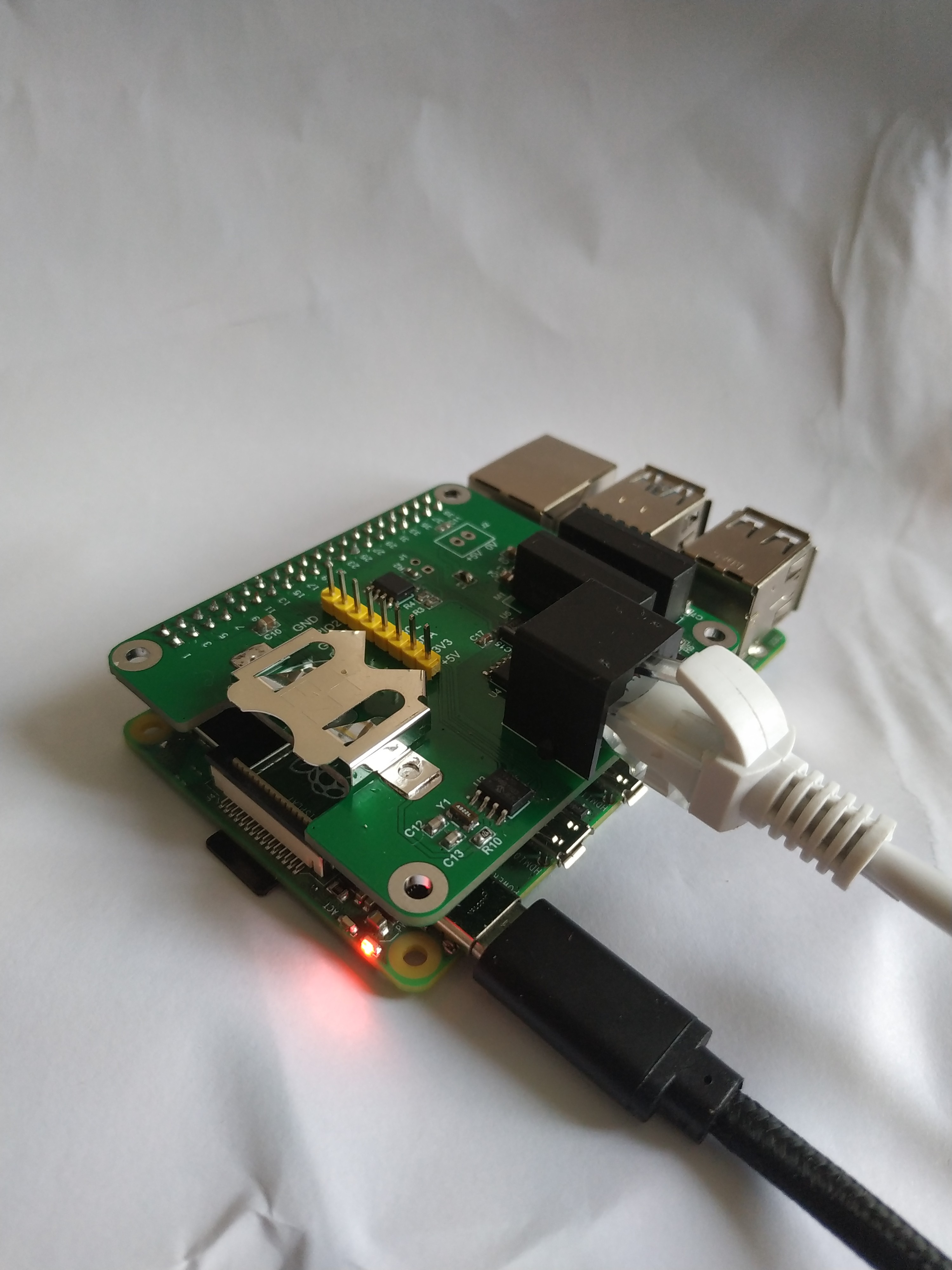
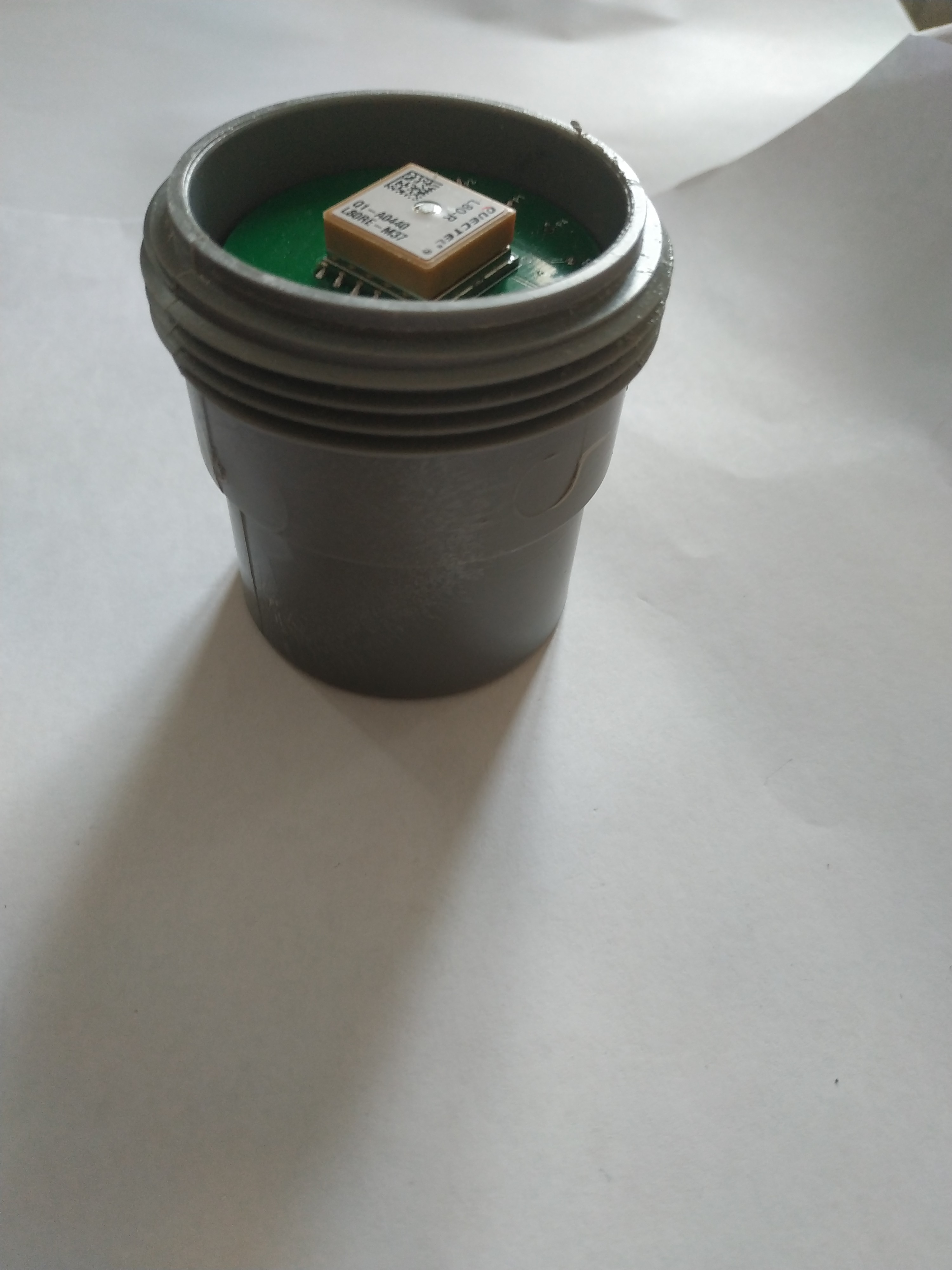
A GPS HAT for Raspberry Pi for easy Stratum 1 Time Server
Become a Hackaday.io member
Already have an account? Log in.
Just one more thing
To make the experience fit your profile, pick a username and tell us what interests you.
Pick an awesome username
hackaday.io/
Your profile's URL: hackaday.io/username. Max 25 alphanumeric characters.
Pick a few interests
Projects that share your interests
People that share your interests


 Ken Yap
 Andrey V
 Thomas Flayols
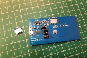
 Sagar 001
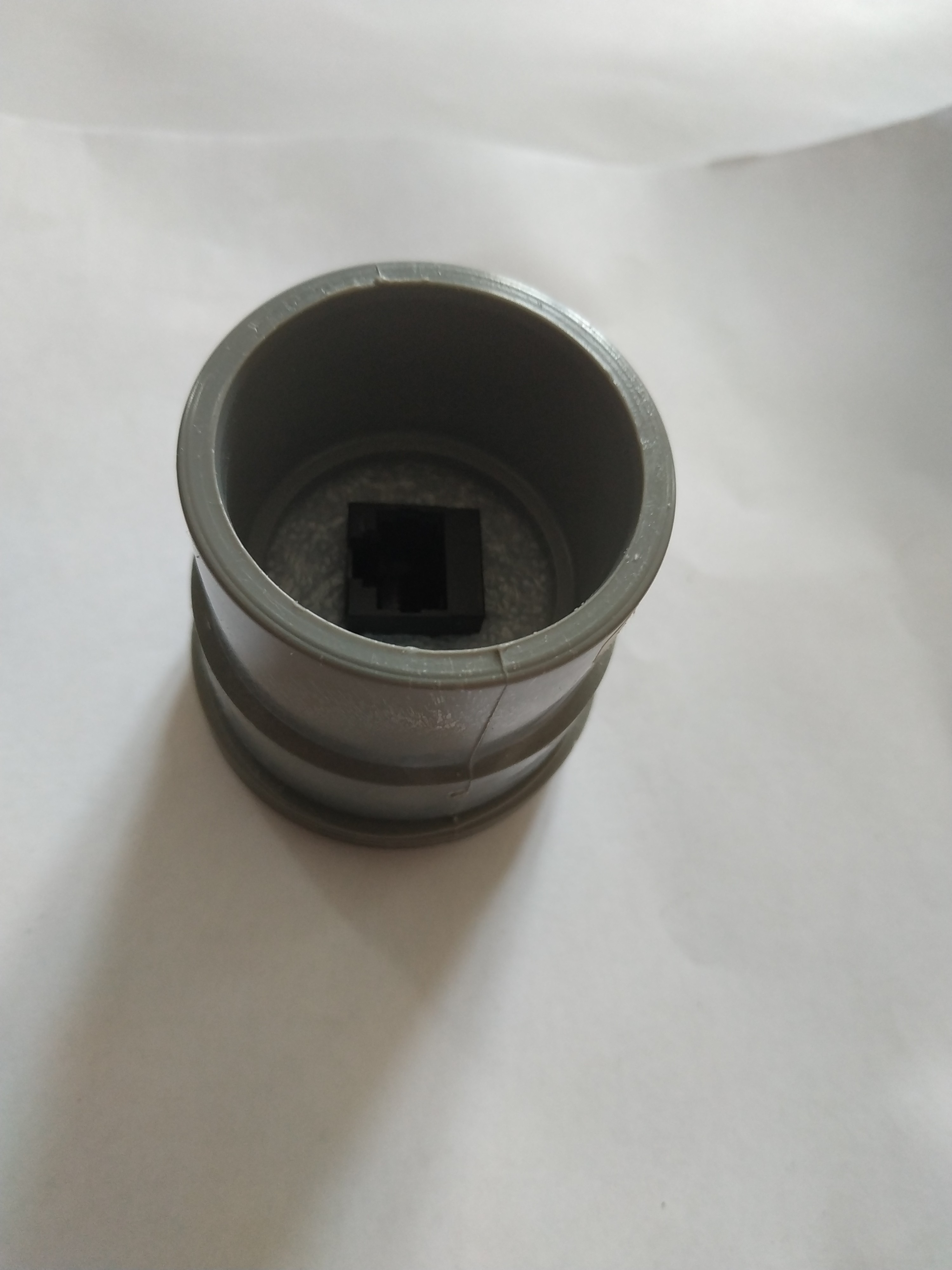
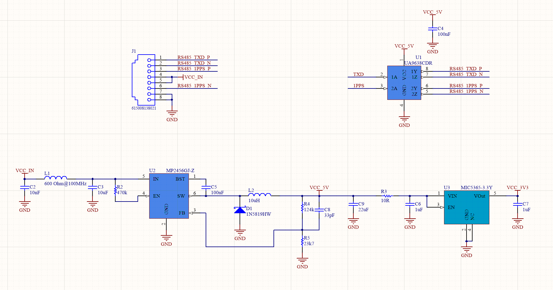
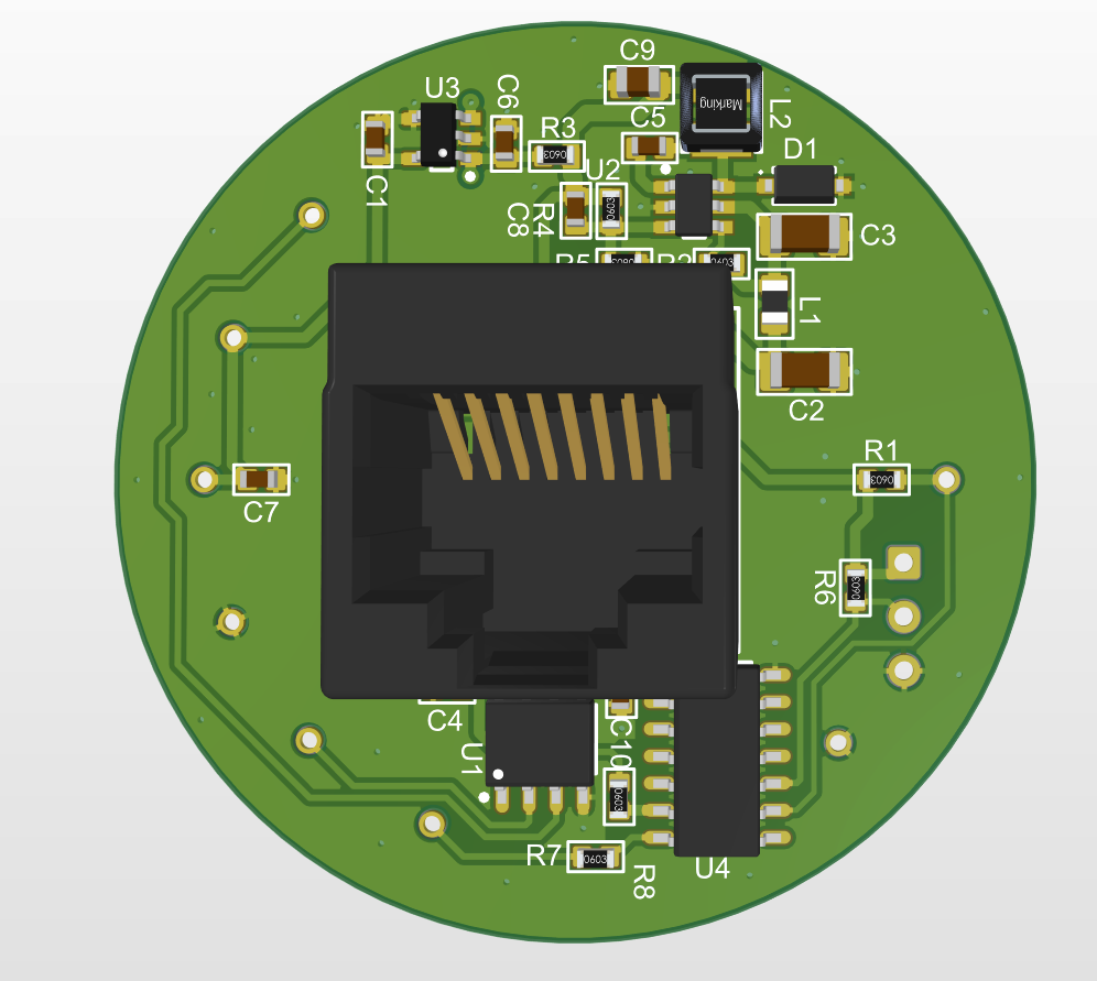
Yes that is exactly that. It uses a GPS module with integrated antenna, and so you can use a cheap Ethernet cable between the GPS Head outside and the raspberry Pi inside. No need for an expensive coax.