 Ben Brooks
My first (recent) microcontroller project turned me onto Particle Photons and got me looking for projects that would specifically benefit from having Wi-Fi functionality. Having recently gotten both security cameras and ‘smart’ lights, being able to have the doorbell trigger them seemed like a logical progression. As mentioned in the description, I didn’t want to alter my existing doorbell setup: partly for aesthetics/functionality but also as an added challenge. The first and primary hurdle was figuring out how to read the (relatively) high voltage AC that powers my doorbells.
A quick primer on wired doorbells: in the U.S., 12V AC is pretty common for powering them. (While I know in my case the transformer is rated for 12V, for whatever reason the voltage that each of my doorbells sees is actually 20V.) A quick google search will show you some diagrams for how things are typically wired. At each doorbell there are 2 wires (20V difference in my case). When the wires are shorted, the doorbell is activated. What this means, is that I needed a way to tell when the voltage difference between the 2 wires at each doorbell went to 0.
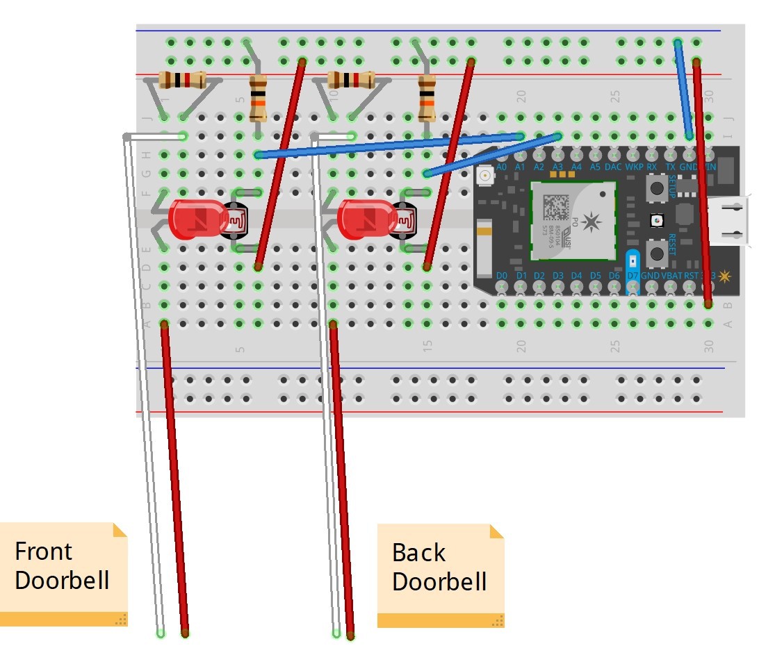
After doing a fair bit of googling to see how other people approached reading the state of a wired doorbell, I was surprised to find very little. I did however stumble upon a forum where someone was attempting to do this (or something similar) and optocouplers were recommended. The forum never resolved whether this worked for the original user but I decided to try it myself. (Optocopulers allow for signal isolation and simply consist of one side driving an LED and another side with a photoresistor reading the state of the LED.) While you can buy pre-made ones for quite cheap, I initially opted for making my own. I should also mention the fact that this would ideally be done with a DC power source on the LED side as AC voltage is constantly pushing and pulling or going high/low, so when directly powering an LED it will flicker (since they only allow current flow in one direction). In the US, this will be at a rate of 60 times a second. Not terribly noticeable to the human eye, but happening nonetheless. At the time I honestly didn’t know if it would meaningfully affect my use.
To test this, I simply took an LED and photoresistor from my parts bin and faced them towards each other, held in place and covered by black electrical tape (being careful to avoid shorting any of the wires). Wiring each up as you normally would (with the LED being driven by the doorbell wiring and the photoresistor being driven by the microcontroller), I was able to read the voltage on the photoresistor side with a multimeter and compare the pressed and un-pressed states. Somewhat to my surprise, my homemade octocoupler worked quite well: I was able to see very clear differences between the two states. Subsequently, I wired in the microcontroller and arranged things so that I got a ‘high’ state when the doorbell was un-pressed and a ‘low’ state when it was pressed. While there was definite variation due to the AC voltage, my photoresistor seemed to lag enough that it stayed pretty constant.
Fast-forward a little further and I was able to wire things up inside the house, connected to the wiring for both doorbells. I put it in a project box (but left it all on a breadboard) and put together some simple code to send Particle Publish commands when either doorbell was rung.
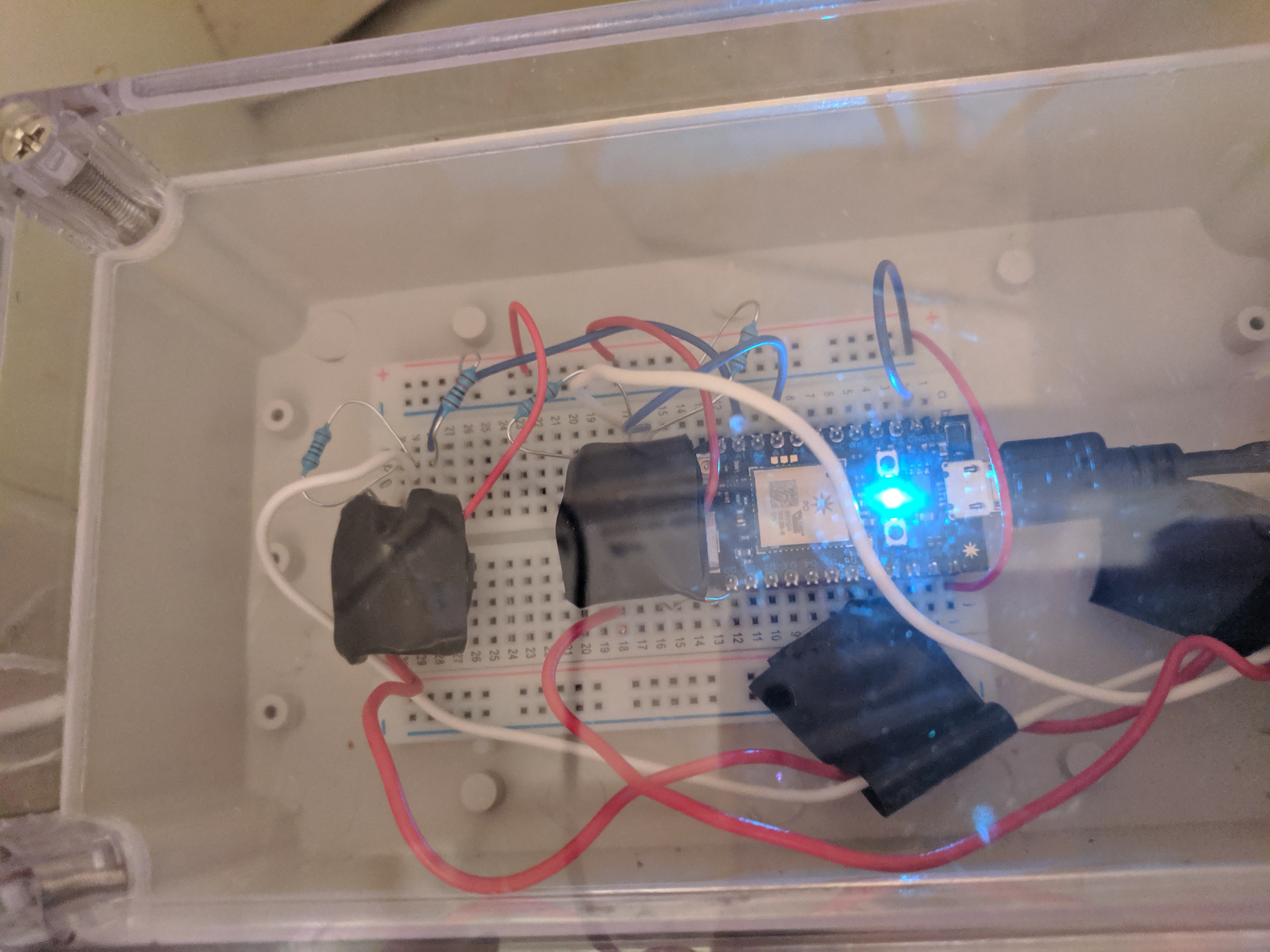
I actually left it this way for quite some time (read: over a year), both to fully test it out but mainly because it was working as-intended. Recently I started playing around with Eagle and designing my own boards; this seemed like a perfect project due to its small size and simplicity (it’d be awfully hard for me to mess up). However, before making a board I definitely wanted to use an actual optocoupler instead of my homemade ones. I found some quite inexpensive ones that fit the bill, ordered them and then proceeded with testing them as I figured they would act a little differently in my circuit.
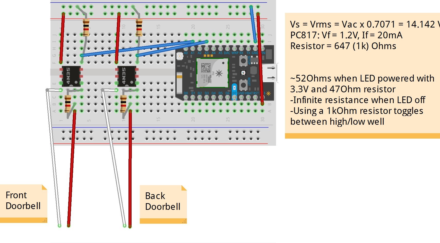
I ran into one main issue when switching to a ‘real’ optocoupler: the frequency response was MUCH higher meaning that the photoresistor read the variation in light output as it flickered due to the AC voltage. Obviously in most cases this would be a huge plus, but not in mine. Ultimately, I was able to deal with this by modifying the code to only trigger a doorbell push when the LED was off for a longer period of time than it was when simply running on the AC voltage.
Initially I setup the code this way and it worked fine but within a few days I noticed that it occasionally triggered errantly. Subsequent logging of the values revealed that in addition to the predictable flicker from the AC voltage, there were slightly longer flickers as well (appeared to always be of a similar length of time). They appeared to be quite random and I was never able to definitively determine the actual cause (my leading theory is very minor power fluctuations, with the similar time lengths being due to automated processes on the utility side of the grid). Regardless, I was able to account for these events as the flicker time was still slightly less than the shortest doorbell press I was able to create/observe.
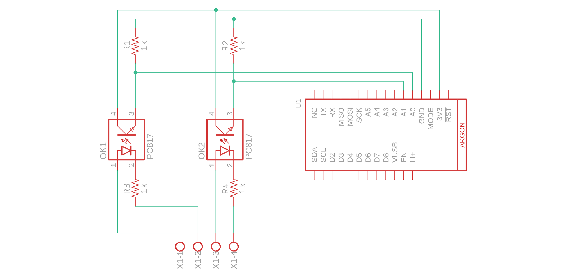
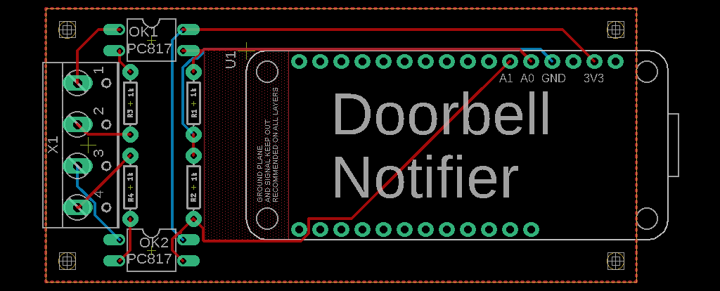
The next step was to design a PCB in Eagle. Originally, I had used a Particle Photon but right around the time I started designing the PCB I was playing around with the new Mesh devices from Particle. I ultimately decided to switch my design to these for several reasons. The primary one was that the layout of the new devices is compatible with the Adafruit Feather line, meaning my PCB would be much more useful for other folks. A lesser reason was that I was still considering whether to leave the Mesh Gateway Device (Argon) as a standalone gateway or integrate it into a static project. This would be a great project to use it for as it’s not at all resource-intensive, it’s centrally located in my house and it’s not ever going to move. Even if it didn’t work out, I could always use a Xenon instead.
This ended up being a great opportunity to learn Eagle and despite my concerns I ended up with a fully-functional PCB on the first try!
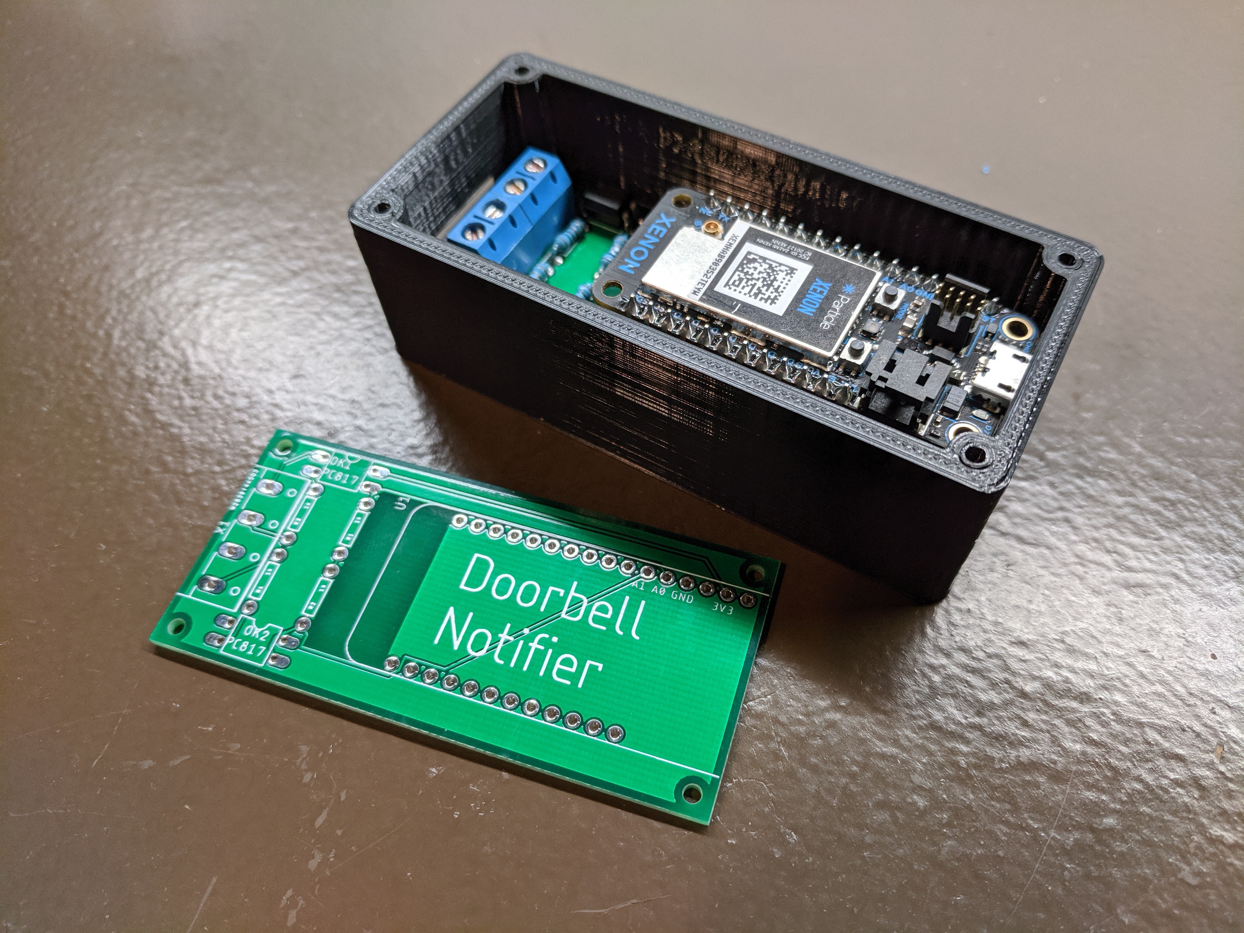
After receiving the PCBs in the mail, I assembled one (ultimately opting to use a Xenon as my microcontroller first) and then designed and printed an enclosure. I should also note that I used stacking headers to allow me to remove the microcontroller without de-soldering so I could easily swap it out if/when I choose to swap out the Xenon with an Argon.
Upon using a new microcontroller with the same code for the first time, I did run into a minor hiccup that took me a few more minutes to rectify than I’d care to admit. The Xenon is a newer device and thus more powerful than the Photon I had used previously. Because I was simply counting cycles rather than actual time, the cycle count for the flickers from the LED running off of AC voltage increased quite a bit (nearly an order of magnitude). Once I adjusted my numbers accordingly, it worked perfectly.
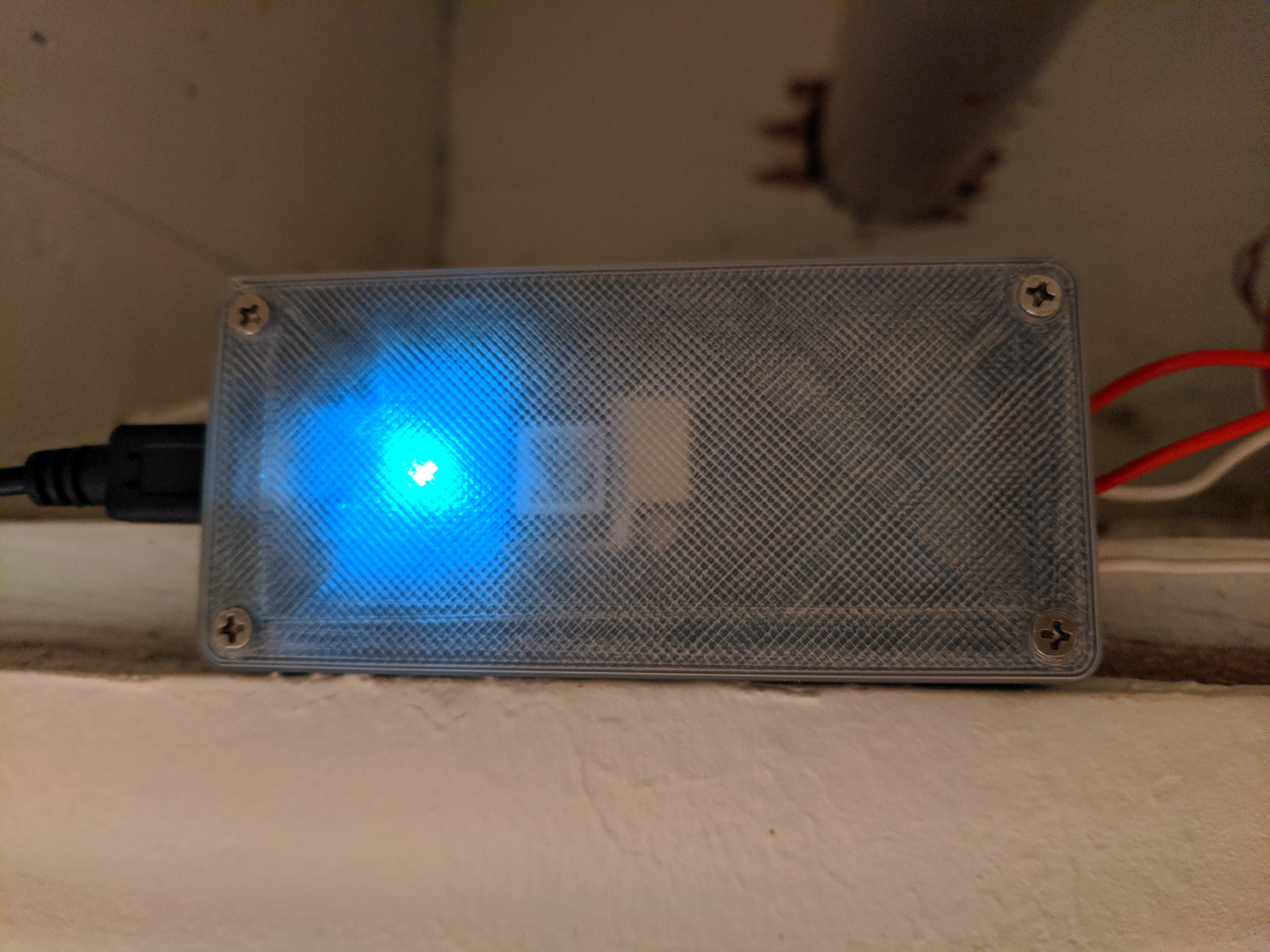
I’m quite happy with the end result. It’s much more robust and professional looking than my breadboard with homemade optocouplers I’ve been using for over a year and it was a great way to learn a few new things: namely designing PCBs in Eagle as well as working with optocouplers to isolate circuits. And I’m still achieving what I originally set out to do: simultaneously trigger the appropriate camera to record on a doorbell press, notify me on my phone, and blink all of the smart lights in my house. I ended up having 10 PCBs made up so I’ve got a number of extras. Obviously, I’ve only got the one doorbell, so if you’re interested in making up this project yourself, hit me up and we’ll figure out a way for me to get one to you. I’ve even got some extra optocouplers if it isn’t a component you have handy.
Future Iterations: I’ve toyed with the possibility of powering the entire thing off of the doorbell wires directly rather than requiring external USB power. In my case it wouldn’t really simplify anything since I’ve already got it setup, but for someone starting from scratch it could greatly simplify the install. If other folks are interested in this I’d definitely be motivated to play around, so let me know if that’s the case!