 land-boards.com
This log will take a look at the changes to the Z80_IO_Handle .c and .h files to support new Peripheral emulations. It can also serve (in part) as a porting guide to run other BIOS code (BIOS in this case being defined as the "stock" code such as ROM Monitors, BASIC language, etc).
Z80_IO_handle.h File
This contains the I/O space memory map from the perspective of the Z80 CPU. These are 8-bit addresses. Each physical port has it's own address. In the case of the SIO this is four addresses:
#define SIOA_D              0x00
#define SIOA_C              0x02
#define SIOB_D              0x01
#define SIOB_C              0x03
These are literally the addresses that are used by I/O routines. From assembly this is IN and OUT opcodes. From [NASCOM] BASIC this is the INP and OUT keywords. Other BASIC interpreters may use other keywords.
The address that needs to be assigned can often be found in the listing file for the stock BIOS code. Since this PIO example isn't working from a standard BIOS build, let's assign the ports. Physically, the PIO gets connected to A/B (Port select) and C/D (Control/Data) select lines. These are Z80 address bits in every instance I have seen. For the SCC, these get connected to A1 = C/D* and A0=B/A*. So, when A1 A0 = 0 0 this is the A port and Data.
Assuming the PIO gets connected in the same basic manner let's "hook" the PIO C/D to A1 and the B/A* to A0. That gives us four ports. Next we need to pick a base address. For the SIO, the base address is zero. We've already got the front panel assigned to 0x18-0x1A. Let's assign the PIO to 0x20-0x23. Of course this should be set to whatever the stock code is but we don't have a particular stock code for this instance (yet).
That translates to:
#define PIOA_D              0x20
#define PIOA_C              0x22
#define PIOB_D              0x21
#define PIOB_C              0x23
Notice how similar this is to the address map of the SIO and how easy it would be to move it. In fact, if we wanted to move the base address trivially, we could use another macro for the base and add an offset. But let's leave off such optimizations for now. They really are just polish on the apple.
The other things in the file are the I/O control bits and some typical patterns. They tell us the details of the transfer type. The one of first interest is the IOBUSY_BIT. This is a bit which reflects the idea that an I/O (or interrupt) operation is in progress and that WAIT* has already been asserted to the Z80. It is made of a combination of the other bits but is a good kick-off point for knowing that a transfer is in progress and the PSoC needs to do something. Here's how it's made:
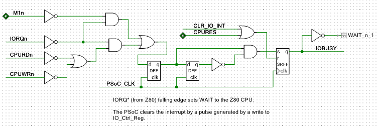 When there is an I/O operation in progress, IORQ* gets asserted (low) by the Z80 and CPURD* or CPUWR* are also asserted. That sets the first Flip-Flop. Another PSoC clock later the second flip flop gets set. The activating edge sets the R-S Flip Flop and gets sent out as WAIT* to the Z80.
 Interrupt acknowledgements are done with M1 and IORQ but without a CPURD* or CPUWR*. They also assert WAIT* to the Z80.
The WAIT* stays asserted until the PSoC clears it with a pulse on the CLR_IO_INT line.
This hardware function is monitored by the loop in main( ) which does nothing more than call the function to handle I/O when it sees IOBUSY set.
        if ((IO_Stat_Reg_Read() & IOBUSY_BIT) == IOBUSY_BIT)
        {
            HandleZ80IO();
        }
The HandleZ80IO( ) function is in Z80_IO_Handle.c . The function first looks at the control bits from the Z80 to determine if the request is an interrupt acknowledgement. If so, it handles the interrupt acknowledgement by sending out the contents of the interrupt vector register to the Z80. Presently, this is only hooked to the SIO Part B Interrupt vector register but if there are other sources (and the PIO could be one such source) it would need to be checked and priority determined (actually it is predetermined and can be found in the interrupt chain on the schematic for the stock design). Then the right interrupt vector would need to be returned. This is another spot where the PSoC can provide some flexibility that other approaches might not be able to incorporate. For instance, the PSoC could ensure that no interrupt source gets starved by higher priority interrupts. Or it could implement a tiered approach where high priority interrupts (like timers) always get serviced first and lower priority sources are handled in another way (maybe, round robined).
The next thing that the HandleZ80IO( ) function has is the switch statement that calls the lower level function. There is a case for every single address defined in the #defines of the memory map earlier. Further, there can be separate calls to read or write functions depending on whether read or write is being asserted by the Z80.
Since the ports are similar to the SIO from the perspective of the Z80 we'll just copy the functions and change SCC to PIO. All the work of emulation will be done at the lower level but this will ensure that the same sort of calls are made as the SIO already uses.
This reduces down to a handful of functions being added. Here's the prototypes for these functions.
void PioReadDataA(void);
void PioWriteDataA(void);
void PioWriteCtrlA(void);
void PioReadDataB(void);
void PioWriteDataB(void);
void PioWriteCtrlB(void);
Discussions
Become a Hackaday.io Member
Create an account to leave a comment. Already have an account? Log In.