0%
0%
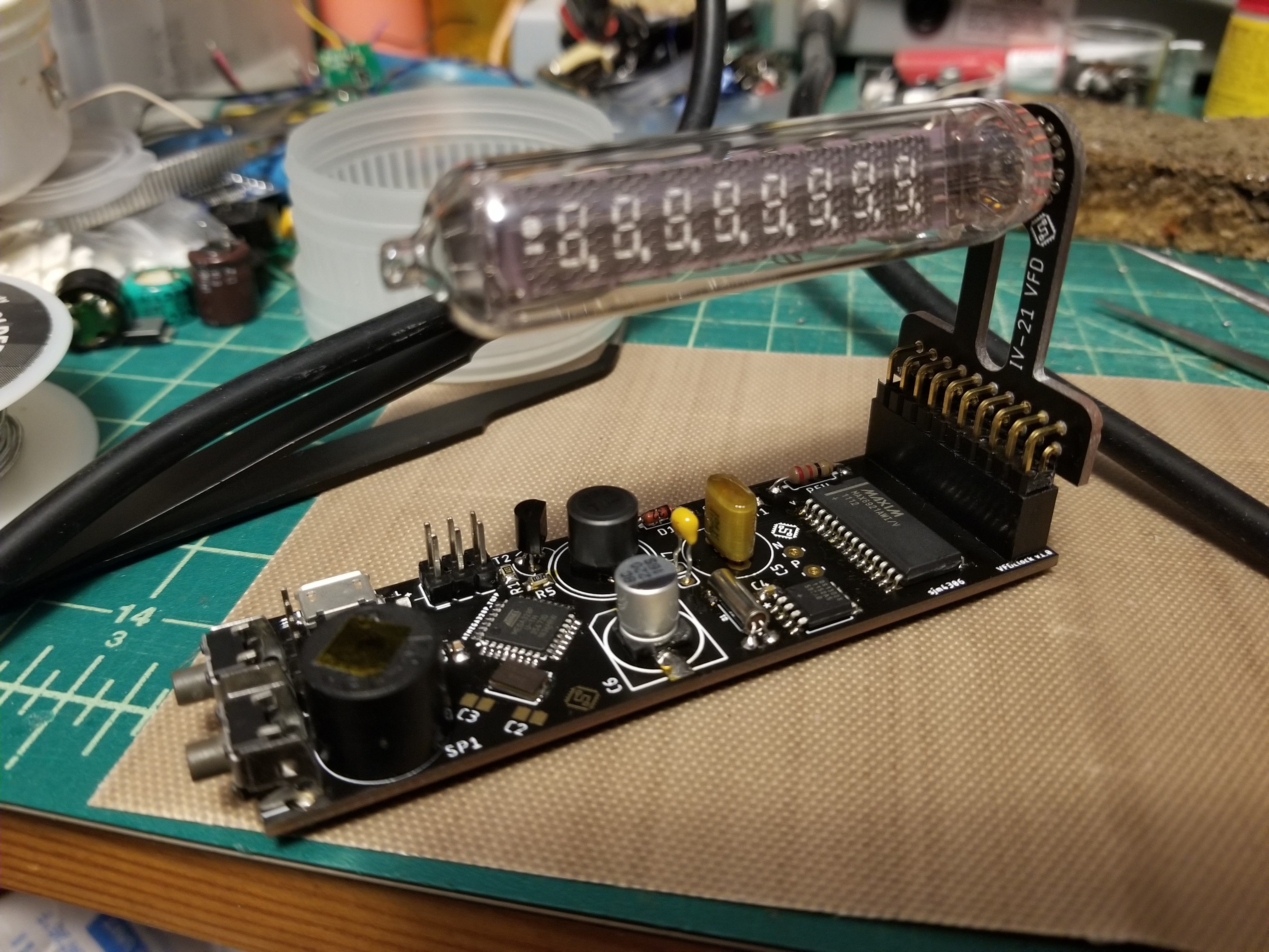
Tiny IV-21 VFD Clock
You can never have too many clocks based on obsolete display technologies ...
 sjm4306
Become a Hackaday.io member
Already have an account? Log in.
Just one more thing
To make the experience fit your profile, pick a username and tell us what interests you.
Pick an awesome username
hackaday.io/
Your profile's URL: hackaday.io/username. Max 25 alphanumeric characters.
Pick a few interests
Projects that share your interests
People that share your interests
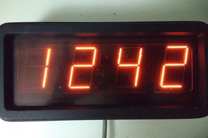
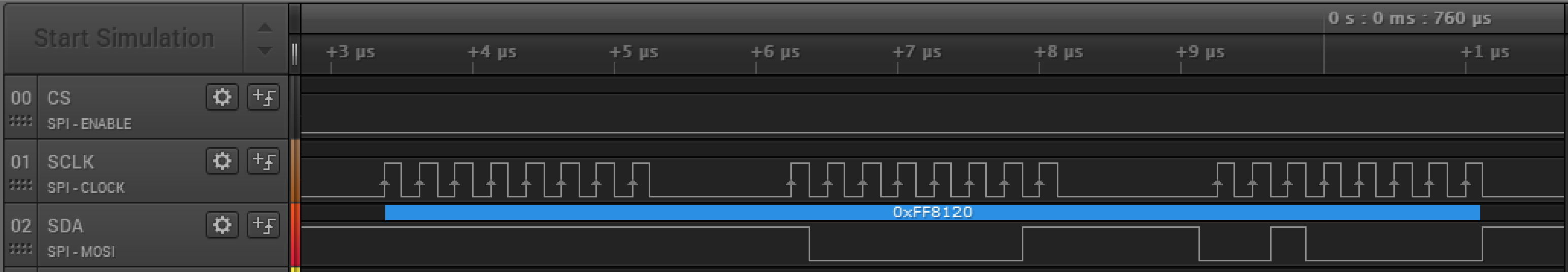 Oddly something is setting the first byte of the SPI packet only for digit 0 (It's 0xFF here but should be 0x00). Anyway once I squash this bug I'll upload all the design files to the project page.


 Ken Yap
 Brainy.Baboon
 Stephen Holdaway
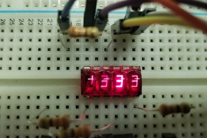
 Jeremy g.
Hello, please help with programming the atmel328. Does the bootloader have to be loaded or not? How should the fuses be set, I set them wrong and the atmel328 is blocked. Thanks Pavel