 land-boards.com
Features List
- Boots instantly
- No waiting for the OS and network to boot
- Identical Pi interfaces
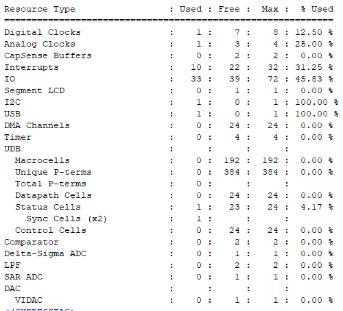
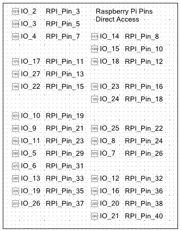
- GPIO
- 3xSPI (can be GPIO)
- 2xI2C (can be GPIO)
- UART (can be GPIO)
- Raspberry Pi hat form factor (65 mm x 56.5 mm)
- Raspberry Pi 40 pin GPIO connector
- Fully compatible with Pi hats
- 3.3V I/O
- 5V to hat (some of our hats do 5V logic translation)
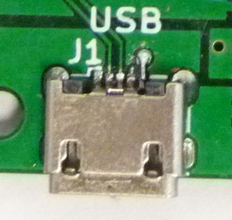
- Micro USB Serial port
- Pi just has a power port
- 5V powers the card just like the Pi
- Located in the same place for use in cases
- Additional I/O connectors - some of them are fixed at 3.3V but one connector can be 3.3V or 5V
- Invulnerable to Pi software changes
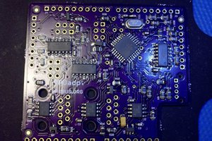
- Programmed in C using PSOC Creator IDE
- Extensive peripheral libraries
- Tons of design examples
- Programmable logic area
- Programmable analog area
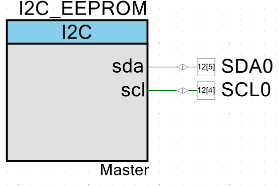 The pins are pre-determined for this I2C interface as above. Dropping the I2C Master symbol onto the PSOC Creator schematic page causes API code to be generated for the I2C master function but the API functions need to be called by the program that needs to use the I2C master.
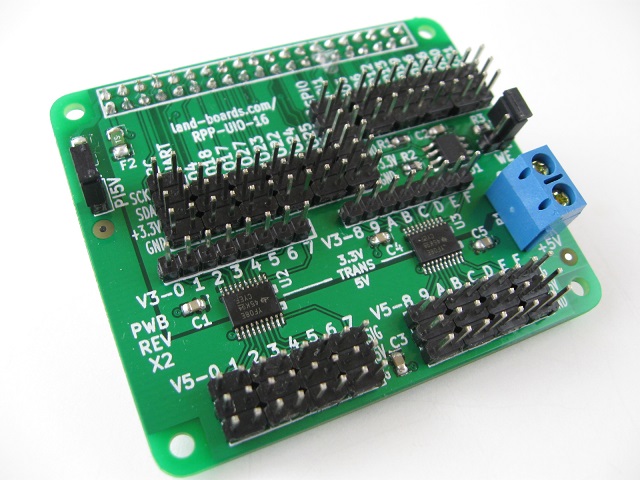

 ronald.sutherland
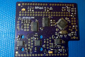
 Muth
Muth
This is a lot like the Pi replacement board that I did a while ago: https://hackaday.io/project/170251-smallpi. Different MCU though. It has been a useful board.