deʃhipu
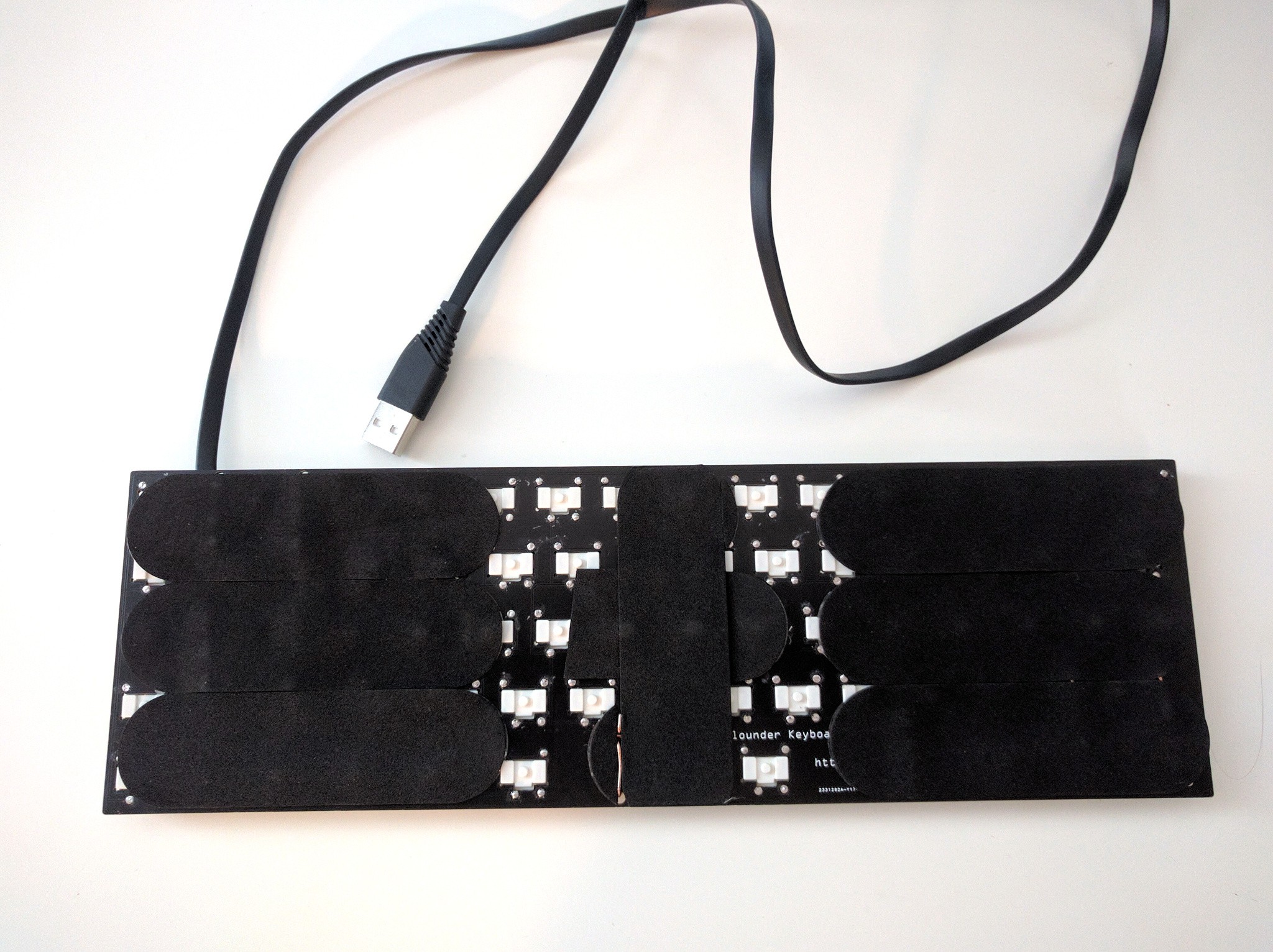
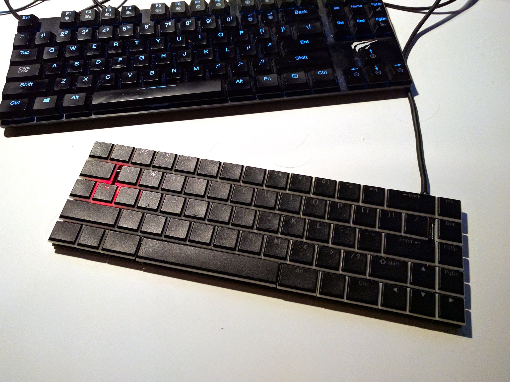
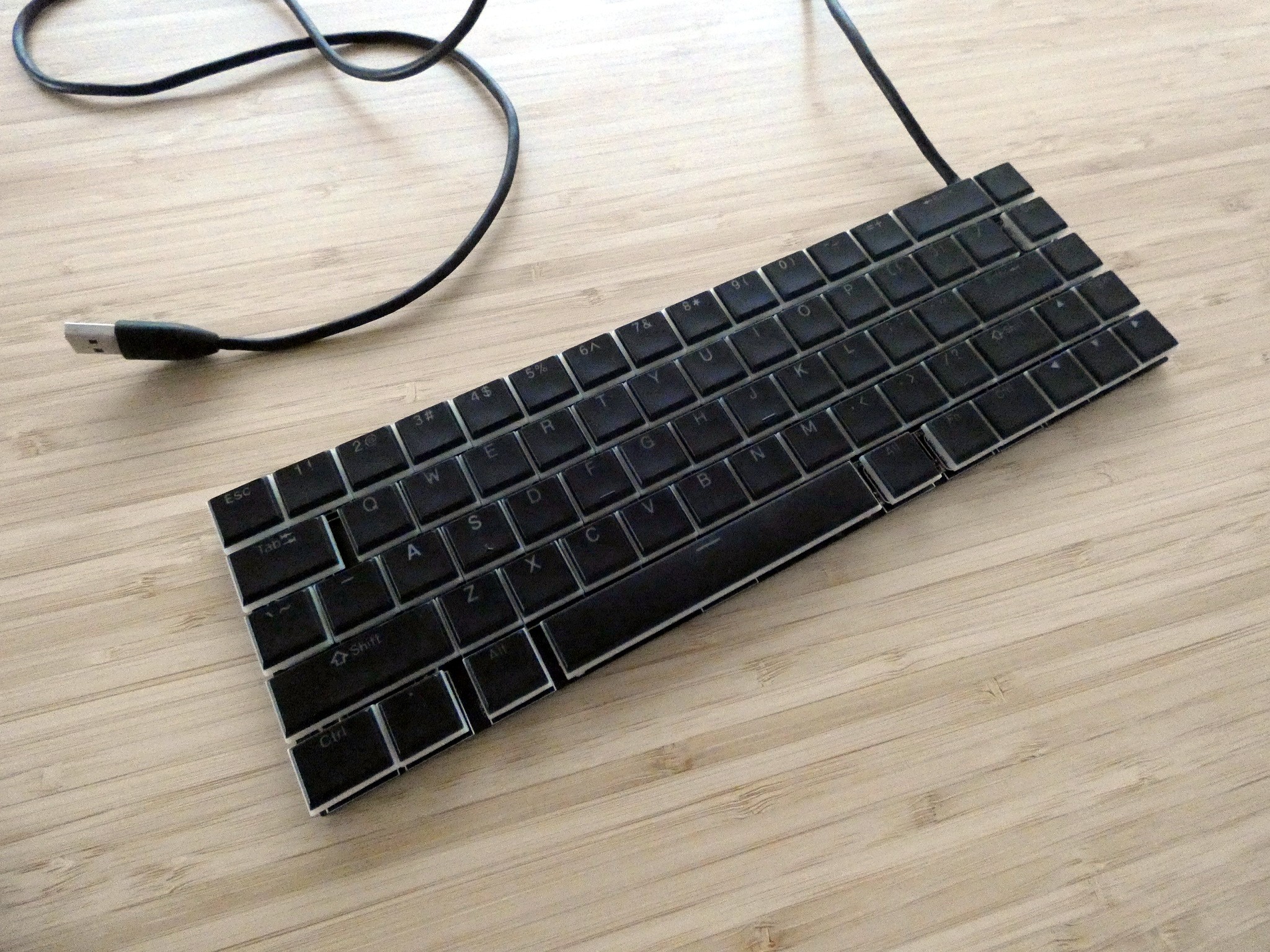
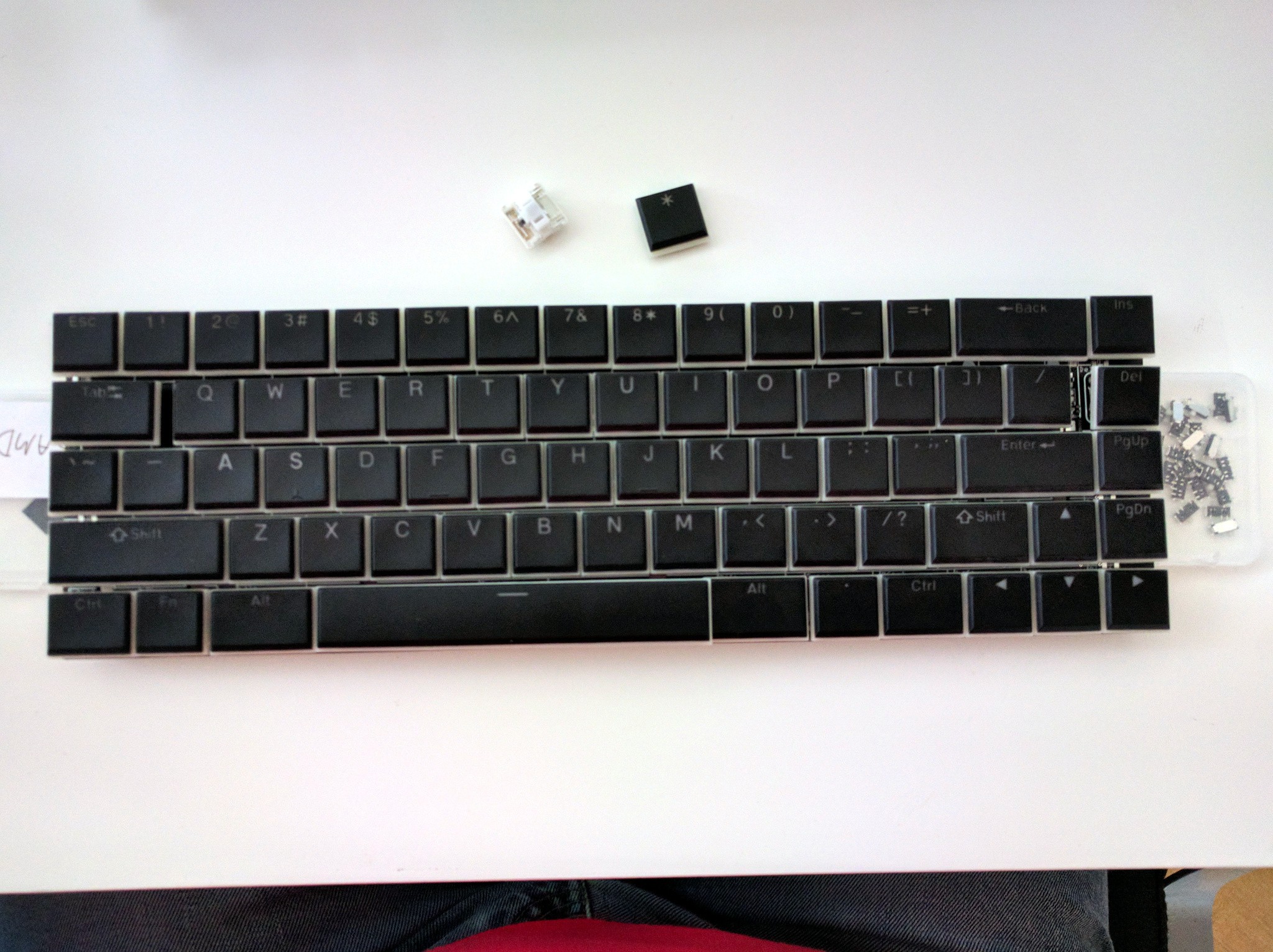
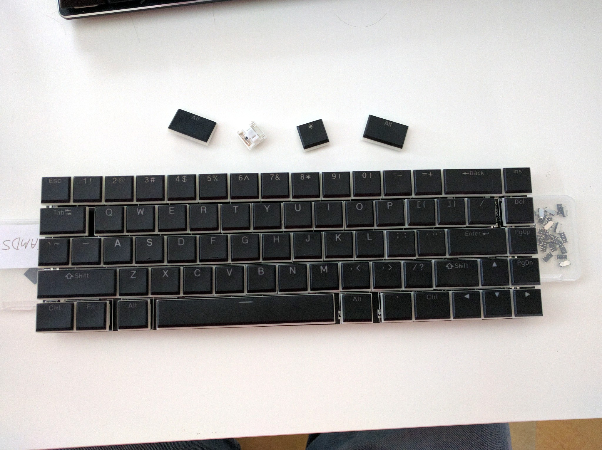
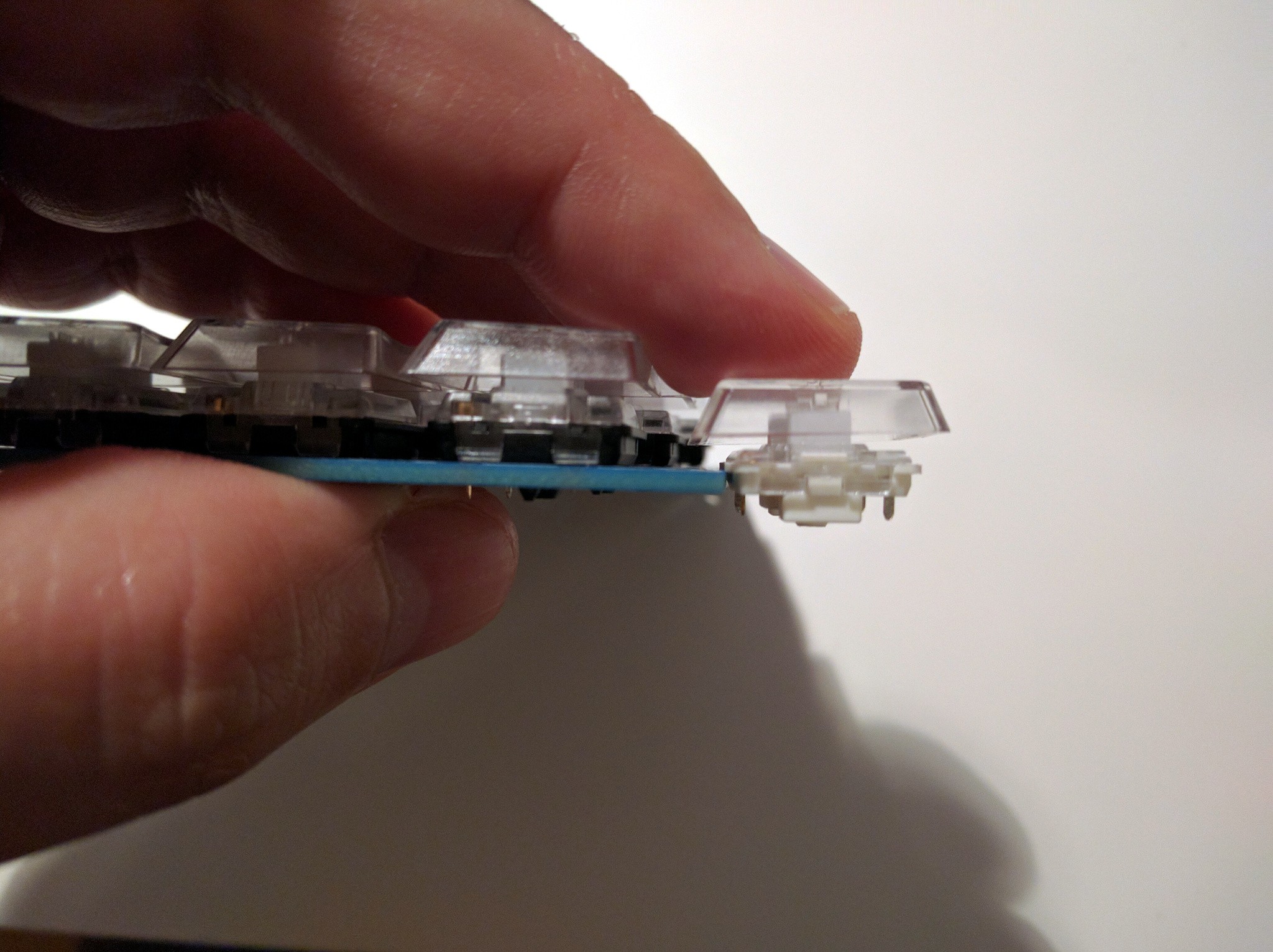
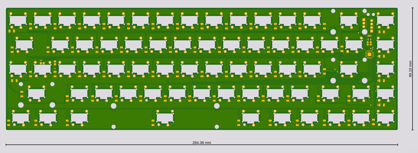
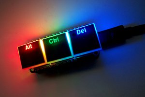
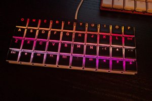
Ever since I saw the low-profile Kailh switches, I couldn't stop thinking about how thin a keyboard would be possible with them, and how it would feel. Now that I found out you can actually buy those switches in small quantities, I decided to try and design a keyboard with them.
0%
0%
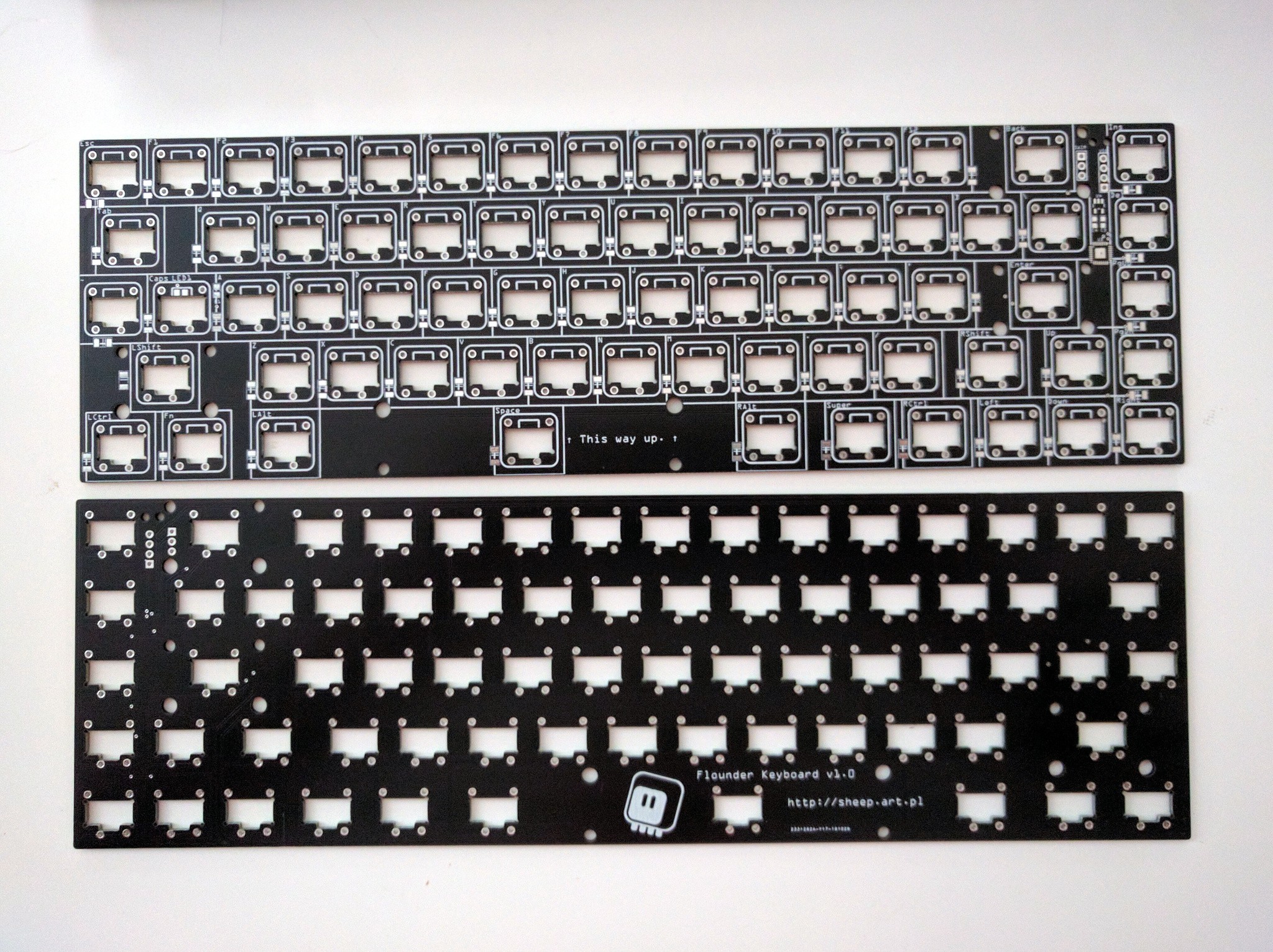
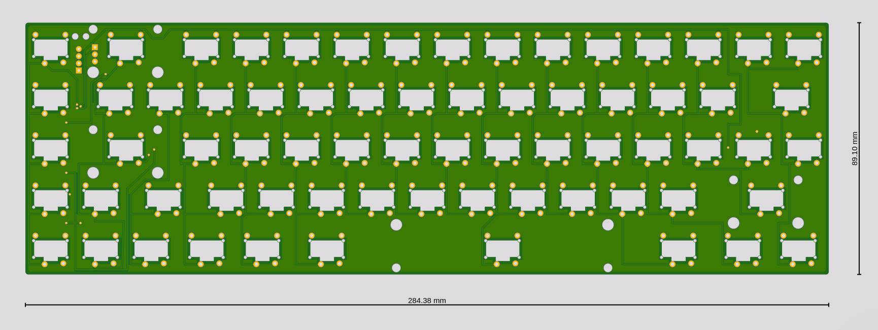
Flounder Keyboard
A low-profile mechanical keyboard
Become a Hackaday.io member
Already have an account? Log in.
Just one more thing
To make the experience fit your profile, pick a username and tell us what interests you.
Pick an awesome username
hackaday.io/
Your profile's URL: hackaday.io/username. Max 25 alphanumeric characters.
Pick a few interests
Projects that share your interests
People that share your interests