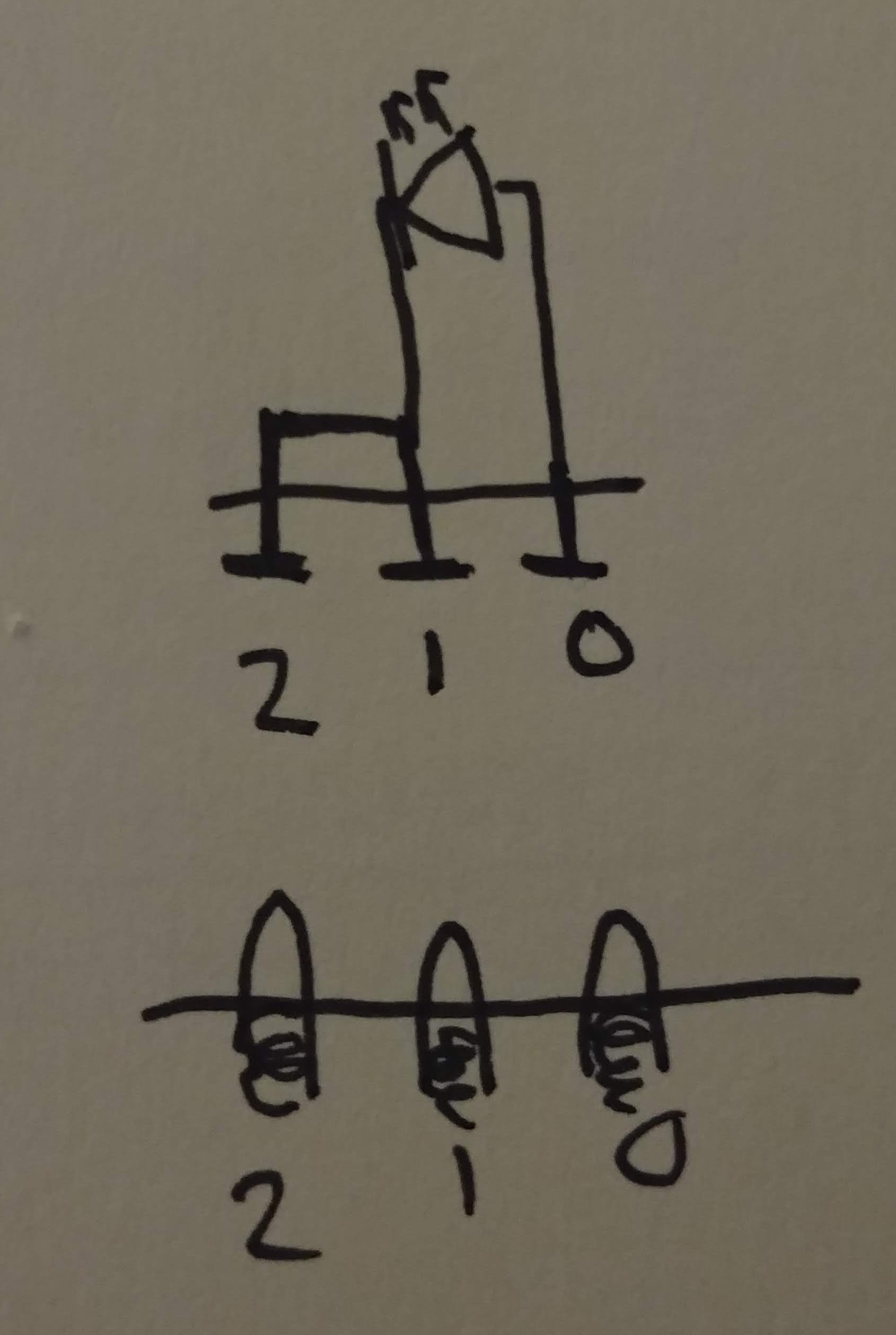
The goal of this project is to use pogo pins (spring-loaded contact pins) connected to an Arduino to power the LEDs in the heart pieces.

There will be two main pieces to the project: the heart base and the removable heart pieces that connect into the base. The heart pieces will connect into the base, and using pogo pins to account for play, the LED will be lit to indicate successful placement of a piece. I borrowed this concept from magnetic connectors that are used to charge devices like smart watches, where the magnets guide the pins to their connection points and keep the connector secured.
The large heart pieces will have 2 magnets per piece, with two matching magnets in the base. This will allow the heart pieces to be secured into the base without fine motor skills, which young children may lack. It will be similar to placing a toy block into its respective shaped hole.
Each heart piece will house an LED, and upon being placed, the LED will light up. To connect the LED to the power/the Arduino, the LED will use contact pads located on the bottom of the heart piece. The contact pads will mate with the corresponding contact pads in the heart base.
There will be 3 pins per LED. Pin 0 will be connected to a digital output pin, which will send a HIGH value to light up the LED. Pin 1 will be connected to ground. Pin 2 will be connected to a digital input pin.

Pin 0 is connected to a digital output pin to allow the microcontroller to send HIGH/LOW values. HIGH will be sent when a connection is detected, and LOW will be sent when the connection is broken. Pin 2 will be acting as the switching mechanism to send these values. I decided to implement it this way to make it safer for children to happen. Even though it is only 5V, it's probably a better idea to have a disconnected circuit if children start poking around with the pins.
Pin 1 will be the ground pin. This serves as the ground for both the LED circuit and the switching mechanism.
Pin 2 is connected to a digital input pin to allow the microcontroller to detect a connection to an LED. I borrowed this concept from a recent project, where I wired a physical switch to ground and a digital input pin. When a connection is detected (circuit completed), then the microcontroller will send a HIGH value to Pin 0 to power on the LED. When disconnected, a LOW value is sent. It is important that I am using an extra pin here (as opposed to a standard 2 pin setup to power an LED) because this will allow the microcontroller to count the amount of LEDs that are connected. Once all 4 heart pieces are put in place (all 4 LEDs connected), a sound will be played to indicate that the children have completed the puzzle correctly.
 Grant Stankaitis
Discussions
Become a Hackaday.io Member
Create an account to leave a comment. Already have an account? Log In.