 Ali
AliElectrical Setup
Additional design improvements can also be integrated into the design’s electrical setup that can improve the pump’s convenience and provide additional features. For example, the electrical setup can be modified to incorporate a potentiometer knob. The knob can be rotated to adjust the input signal to the microcontroller which can automatically equate to changing the initially set flow rate value in the code. As a result, this will allow the user to adjust the flow rate during operation without the need to reconfigure the microcontroller’s code.
An addition of a liquid crystal display (LCD) screen can allow the user to view details about the pump when running, such as the currently set flow rate or the operating time remaining.
Furthermore, a toggle switch can be included to override the controller’s code and act as a safety off switch. It can alternatively be used to select between the controller’s codes. This can allow the pump to have separate functioning modes such as high and low speeds or small and large volumes. Enabling the user to quickly interchange between the modes depending on the desired task without the need to reconfigure the controller’s code.
Design Optimisations
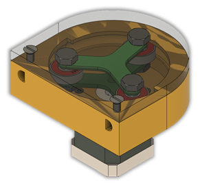
Additional design upgrades can be implemented to improve the durability and functionality of the pump. For example, a plastic cover that can be fixed onto the top of the pump, shown in the figure below, can provide protection to the pump’s components such as the tubing and rotor. It can also prevent unwanted objects from entering into the casing, which can impede the rotor or tubing and can cause damage to them or leakage. The purpose of having a transparent cover is to enable the user to quickly inspect the inside of the casing for any potential leakage, thus improving the chance of identifying faults before they develop further.
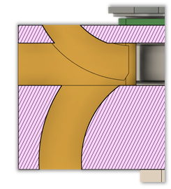
The number of inlet and outlet holes for the tubing can be increased, as shown in the figure below, from the current case where there is only a single inlet and outlet hole. This will allow the direction of the tubing to be adjusted according to the application’s need, which will reduce the risk of the tubing getting pinched due to sudden change in direction as it exits or enters the pump that can accelerate tubing wear.
Finally, a housing for the electrical components can be created to contain the microcontroller and other fragile electrical components such as the motor driver and capacitor. This will give the design further durability and increase the project’s portability as the entire housing can be simply moved instead of each component separately.
Discussions
Become a Hackaday.io Member
Create an account to leave a comment. Already have an account? Log In.