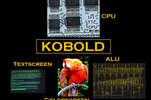
Suite-16
Suite-16 arose from my curiosity regarding how computers work.
I have had a lifetime in hardware engineering but very little real exposure to firmware and software since my Z80 coding days in the 1980s.
The Suite-16 project will encourage me to explore the interactions of hardware, firmware and software - hopefully widening my horizons, learning new skills and achieving the goal of building a working TTL computer system.
Suite-16 refers literally to the suite of deliverables needed to put together a working 16-bit computer system.
The main deliverable will be a 16-bit computer system designed and built from 7400 series TTL integrated circuits outlined in the next section below.
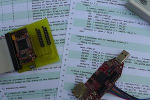
From a hardware point of view this will include circuit schematics, pcb layouts, timing diagrams and test-bench programs. It will also likely contain FPGA prototypes with their supporting designs coded in verilog. Part of the project aim is to become familiar with FPGA design and verilog programming - and what better way than to set the goal of a working computer system.
As any computer is the co-ordinated interaction between hardware and software - there will be several key software deliverables needed to complete the design. These will include the Instruction Set - Architecture or ISA, an assembler and a software simulator of the proposed machine. Later on, when the machine is debugged and can run simple code - there will be applications to be written such as high level languages.
You can find my Github repository here: Suite-16 This is updated regularly to include all the latest Arduino code and sketches.
In summary, Suite-16 is an exploration of the knowledge space bounded by hardware, software and FPGA design.
Main Features
Principle Technology: 5V TTL logic with conventional through-hole DIL packages wherever possible
Data bus: 16-bits
Address bus: 16-bits - with possible extension to 24-bits
Architecture: Von Neuman Accumulator-Register
Hardwired Logic - no microcode
Basic 2 stage pipeline allowing most instructions to complete in 1 clock cycle
Registers: 16 general purpose registers R0 to R15. R0 is the accumulator, most ALU operations are on Accumulator and a Register
Additional Registers: Program Counter PC, Instruction Register IR
Number of instructions: 31
ALU Instructions: ADD SUB INC DEC COM AND OR XOR
Memory and Register Instructions: SET LD ST LD@ ST@ POP PUSH
Program Flow: CALL RET JMP BRA and conditional branching BGT BLT BNE BEQ BGE BLE
Other Instructions: IN OUT SRA SLA CLA STC CLC
Addressing Modes: Immediate #N, Register Direct Rn, Register Indirect @Rn, Indirect Autoincrement @Rn+, Indexed Mode (Rn+X), Symbolic Mode (PC +X)
Instruction Length: 16-bits
Instruction Format: 8-bit bytecode in IR 15:8 augmented by 8-bit payload in IR 7:0
Hardware: ALU based on 4-bit bitslice design. ALU + PC plus register file on one pcb. Memory and mass-storage on 2nd pcb.
Performance: Aiming for 12.5MHz clock frequency to have some interoperability with VGA video systems.
Target Use: Co-processor / Accelerator for accompanying TTL colour computer (Gigatron)
Tools and Resources.
Throughout this project I will need to learn new techniques and use new tools.
Hardware simulation will be done using H. Neeman's "Digital" simulator - which is an updated version of Logisim https://github.com/hneemann/Digital
Most of my C code will be run on Arduino compatible platforms - so that it can easily be explored.
For hardware schematics and pcb layout, I generally use EagleCAD 6.x - but I am slowly moving towards open source tools including KiCAD and the online pcb design package from easyEDA https://easyeda.com/
Sometimes we have to resort to FPGAs and a suitable hardware description...
Read more »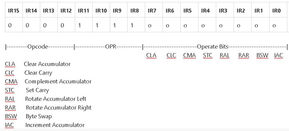


 Ed S
Ed S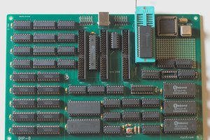
 kaimac
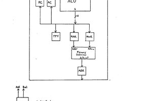
I'm just watching this great presentation on an alternative 16-bit processor for the 6502. https://www.youtube.com/watch?v=zdJnz6-d060 AcheronVM. There're some good ideas in there I would certainly play with if I were doing vCPU again.