Key to the operation of the machine is the Instruction Set.
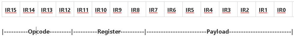
Suite-16 uses a 16-bit wide instruction word format which is separated into various bitfields.
The instruction exists as an 8-bit wide bytecode located in the upper byte of the Instruction Register IR15:8 and an 8-bit payload byte in IR7:0.
The Operation is encoded into the bitfield IR15:12, and the Register Rn is encoded into bitfield IR11:8.
Here is the Instruction Set as it currently stands:
/* Suite-16 Instructions

Register OPS-

         0n        ---       --     Non-Register Ops
         1n        SET       Rn     Set Constant        Rn = @(PC+1)
         2n        LD        Rn     Load                AC = Rn
         3n        ST        Rn     Store               Rn = AC
         4n        LDI       @Rn    Load Indirect       AC = @Rn
         5n        STI       @Rn    Store Indirect      @Rn = AC
         6n        POP       @Rn    Pop  AC             AC = @Rn  Rn = Rn - 1
         7n        PUSH      @Rn    Push AC             @Rn = AC  Rn = Rn + 1
         8n        AND       Rn     AND                 AC = AC & Rn
         9n        OR        Rn     OR                  AC = AC | Rn
         An        ADD       Rn     Add                 AC = AC + Rn
         Bn        SUB       Rn     Sub                 AC = AC - Rn
         Cn        CPR       Rn     Compare             AC = AC - Rn  R13 = flags
         Dn        DEC       Rn     Decrement           Rn = Rn - 1
         En        INC       Rn     Increment           Rn = Rn + 1
         Fn        XOR       Rn     XOR                 AC = AC ^ Rn

Non-register OPS-

         00        JMP    16-bit                        Target = @(PC+1)
         01        BGT    AC>0                          Target = IR7:0
         02        BLT    AC<0                          Target = IR7:0
         03        BNE    AC!=0                         Target = IR7:0
         04        BEQ    AC=0                          Target = IR7:0
         05        BGE    AC>=0                         Target = IR7:0
         06        BLT    AC<=0                         Target = IR7:0
         07        BRA    Always                        Target = IR7:0
         08        CALL   16-bit                        Target = @(PC+1)
         09        RET    Return
         0A               Unassigned
         0B               Unassigned
         0C               Unassigned
         0D               Unassigned
         0E               Unassigned
         0F               Unassigned

     */
Instruction Decoding
I have made some subtle changes to the order of the instructions, which I think may simplify instruction decoding.
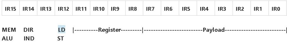
Firstly instructions that access memory or registers are in the lower half of the Opcode group when IR15 is zero.
Those that involve ALU operations are in the upper half of the Opcode group when IR15 is set.
Opcodes 0n to 3n all deal with the register direct, 4n to 7n all deal with the register indirect. This means that bit IR14 of the instruction register can be used to signify direct or indirect register addressing modes, when combined with the condition that IR15=0.
In a similar way, bit IR12 can be used to differentiate between operations that load the accumulator AC and those that store the Accumulator. IR12 becomes effectively a !RD/WR indication when combined with the condition IR15=0 and IR14=0
There is no real logical pattern to the ALU operations, except that I wanted some mnemonic value - A for Add, B for suB, C for Compare, D for Dec. It rather falls apart after that, except E could be for Exclusive OR.
I'm still not certain whether the Compare operation is really justified, after all it is really just a variant of subtraction.
Notes
There are at most 31 instructions, which can be divided into the following groups:
Register/Memory Transfer 7 instructions
Register/ALU Operations 8 instructions
Program Flow Control 10 Instructions
Unassigned 6 Instructions
With just 31 instructions, Suite-16 could qualify as being a mimimum instruction set computer - or MISC.
Instructions form 2 main groups - those that are Register Operations, and those that are Non-Register Operations
The Register Operations are further divided into Register/Memory ops and Register/ALU ops.
Register/Memory instructions form the basis of immediate, register direct and register indirect addressing modes. I have included a Push and Pop which supports Accumulator transfer to register indirect addressed memory combined with an auto-increment or decrement of the designated register.
The Register/ALU operations are defined entirely by the current capability of the ALU. Other operations may be possible - such as shift right, clear and complement, but hardware restrictions in instruction decoding will mean that these operations can only work on the Accumulator.
The non-Register Operations are mainly concerned with program flow, Branching, Conditional Branching, Call and Return.
Branching has a span of +/-128 addresses to either side of the current Program counter - with the Program Counter offset being contained in the lower 8-bits of the Instruction Register IR7:0.
Subroutine Call, and absolute Jump have an absolute address range of 16-bits - and the target address is contained in the next memory word at (PC+1).
So far the Call and Jump instructions do not use the lower 8-bits of the Instruction Register IR7:0. These unused bits could possibly be used to extend the addressing range to a full 24-bits, or 65,536 pages of 256 words. Paged memory has been around for a long time as a cost effective way of being able to address more memory - but without having to extend all of the data bus widths of the registers.
This is an intriguing concept for extending the scope of the whole machine. Memory is cheap these days - and the whole 16M x 16 could be populated for under $150.
Memory could be addressed as a linear model, consisting of 256 pages of 64K. This would be one way of partitioning the memory to support relatively few large applications - running in separate 64K pages. The other extreme is to have an object model - where memory supports a large number (64K) of small 256 word objects. This alternative arrangement may be useful for supporting modern object-oriented languages, CAD programs where objects drawn on the screen have their properties coded as separate objects in memory or for languages such as Forth - where each Forth Word, is coded into a small page of memory and addressed by a 16-bit pointer. Thanks to Roelh and his Kobold 2 project for explaining these different memory models https://hackaday.io/project/167605-kobold-k2-risc-ttl-computer/log/168785-accessing-memory
The last six instructions of the non-Register operations are currently unassigned. These will probably be used for Input/Output operations, manipulating the accumulator contents directly, or used in a similar manner to the PDP-8 OPR instructions which are used to control the hardware directly.
Discussions
Become a Hackaday.io Member
Create an account to leave a comment. Already have an account? Log In.
Hi Ken, I changed the memory model of Kobold K2, and then changed its description in the log "accessing memory". Your reference to that log might no longer be accurate.
Are you sure? yes | no